Smart Home / Smart Switches
User Manual for TechniSat 0x00-9499 Smart Flush Mounted Switch
Quick guide for the TechniSat 0x00-9499 Smart Flush Mounted Switch. Learn about installation, Z-Wave network integration, configuration parameters, and technical specifications.
Table of contents
Manual images
Click an image to enlargeQuick guide from the manual
The TechniSat 0x00-9499 is a flush-mounted smart switch designed for Z-Wave networks. It allows for remote control of connected consumers (e.g., lights), energy consumption measurement, and scene control. Installation must be performed by trained personnel (electricians) in accordance with safety regulations. Always disconnect the mains power at the fuse before installation.
Device overview
The device features two push-button positions (T1 and T2) and a status LED. The LED indicates network status: red means logged in, flashing red indicates an overload, and green (for 5 seconds) confirms successful login.
Installation and wiring
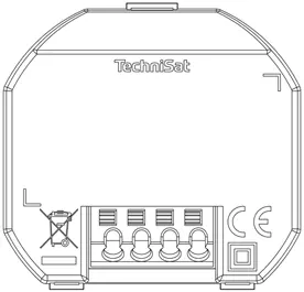
The switch is designed for installation in flush-mounted boxes (DIN 49073-1). Terminals accept cables of 1.5 mm² (fixed) or 1 mm² (flexible with clamping sleeve). Conductors must be stripped by 10 mm. The device requires connection to Phase (L), Neutral (N), Switched output (L1), and an optional Auxiliary input (S) for external switches or push-buttons.
Z-Wave integration
SmartStart setup: Scan the QR code located on the back of the product, the manual cover, or the device box using your primary Z-Wave controller and smartphone camera. After scanning, it may take up to 10 minutes for the device to be added.
Manual set-up: Set your primary Z-Wave controller to inclusion mode. Press the upper push-button (T1) 3 times within one second. The LED will light up red during the process and green for 5 seconds upon success.
Removing/Resetting: To remove from the network, set the controller to exclusion mode and hold T1 for at least 10 seconds. To reset the device (only if the controller is missing), hold the lower push-button (T2) for at least 20 seconds.
Configuration
The device supports several configuration parameters via the Z-Wave controller, including:
- Parameter 1: Central scene notification (0=Deactivated, 1=Activated).
- Parameter 2: Power consumption message interval (3-8640).
- Parameter 3: Energy consumption message interval (10-30240).
- Parameter 4: Function of T1/T2 buttons.
- Parameter 5: Switch configuration at auxiliary input S (0=Switch, 1=Push-button).
- Parameter 6: Central scene assignment to auxiliary input S.
Technical data
The device operates at 230 V AC, 50 Hz, with a nominal load current of 5 A. It is rated IP20 for indoor use and has an operating temperature range of +5 °C to +35 °C. It is compatible with Merten M1, Busch-Jaeger Duro 2000, and Gira System 55 series switch systems.
Practical help
Common problems
Device not adding to Z-Wave network
Ensure the controller is in inclusion mode and press the upper push-button (T1) 3 times within one second.
Overload detected
The LED flashes red. Check the load connected to L1; the maximum permissible load has been exceeded.
Need to reset the device
Hold the lower push-button (T2) for at least 20 seconds. Only do this if the primary controller is missing or non-functional.
Before use
- Ensure mains power is disconnected at the fuse.
- Verify the flush-mounted box meets DIN 49073-1 standards.
- Strip conductors by 10 mm.
- Ensure cables are 1.5 mm² (fixed) or 1 mm² (flexible).
- Confirm the load is within the 5A limit.
Specs in practice
- Power supply
- 230 V AC, 50 Hz (+/- 10%).
- Output nominal load current
- 5 A maximum.
- Protection type
- IP20 (indoor use only).
- Operating height
- Below 2,000 m above sea level.
Images and diagrams
- Wiring diagram: Shows connections for Phase (L), Neutral (N), Switched output (L1), and Auxiliary input (S).
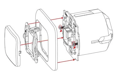
- Installation: Exploded view showing the assembly of the rocker switch, frame, balancing frame, and the switch module.
Model compatibility
- Compatible with Merten M1 series.
- Compatible with Busch-Jaeger Duro 2000 series.
- Compatible with Gira System 55 series.

Manual page author
David Miller
Documentation analyst
Organizes user manual content into clear summaries, with attention to model details, product context, and everyday usability.