Power / Transformers & Supplies
Thermaltake TOUGHPOWER GT 1200W / 1000W Power Supply User Manual
Quick guide and user manual for the Thermaltake TOUGHPOWER GT 1200W and 1000W power supply units. Includes installation steps, connector details, troubleshooting, and safety warnings.
Table of contents
Manual images
Click an image to enlargeImportant Information
This manual provides instructions for the Thermaltake TOUGHPOWER GT series power supply units (1200W and 1000W models). It covers safety precautions, installation procedures, connector configurations, and troubleshooting steps. Always ensure the power supply is compatible with your system's power requirements before installation.
Safety Warnings
- Do not open the power supply case: High voltages exist inside. Opening the case voids the warranty unless performed by an authorized technician.
- Power Source: Use only the power source indicated on the rating label.
- Cable Compatibility: Use only genuine Thermaltake modular cables. Third-party cables may not be compatible and can cause serious damage to your system and the power supply.
- Environment: Do not place the power supply in high humidity or high-temperature environments.
- Handling: Do not unplug the AC power cord while the power supply is in use, as this may damage components.
Components and Connectors
The TOUGHPOWER GT series features a fully modular design. The number of connectors varies by model (1200W vs 1000W). Key connectors include:
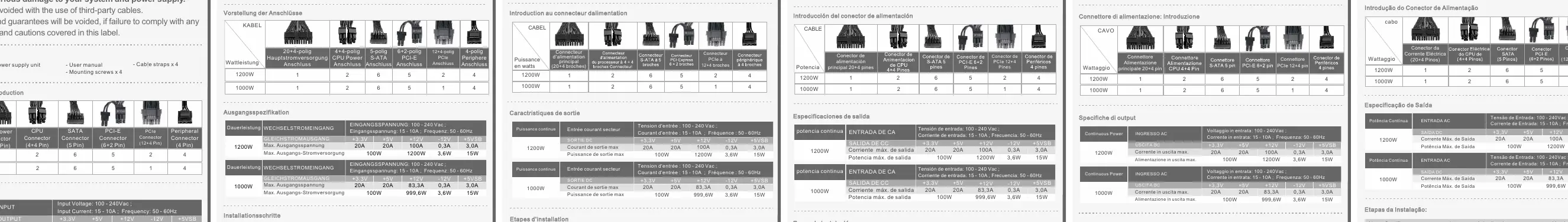
- 24-pin: Main motherboard power connector.
- ATX 12V (4+4 pin): CPU power connector.
- PCI-E (6+2 pin): Graphics card power connector. This unique connector can be used as either an 8-pin or 6-pin connector. To use as a 6-pin, detach the 2-pin section.
- SATA (5 pin): Power for hard drives and optical drives.
- Peripheral (4 pin): Power for other peripheral devices.
Installation Steps
- Ensure the computer is turned off and unplugged.
- Disconnect the AC power cord from your old power supply.
- Connect the 24-pin or 20-pin main power cable to the motherboard.
- Connect the 4+4 pin ATX 12V cable to the motherboard. If your motherboard requires only a 4-pin connector, detach the 4-pin section from the 4+4 pin connector.
- Connect power cables to peripheral devices like hard drives and optical drives.
- Connect the necessary PCI-E cables to your graphics card. Use the 6+2 pin connector as required by your card.
- Close the computer case and connect the AC power cord to the power supply.
Troubleshooting
If the power supply fails to function properly, check the following before contacting support:
- Ensure the AC power cord is properly plugged into the wall outlet and the power supply.
- Verify that the I/O switch on the back of the power supply is in the 'I' (On) position.
- Check that all power connectors are securely attached to all devices.
- If connected to a UPS, ensure the UPS is turned on and plugged in.
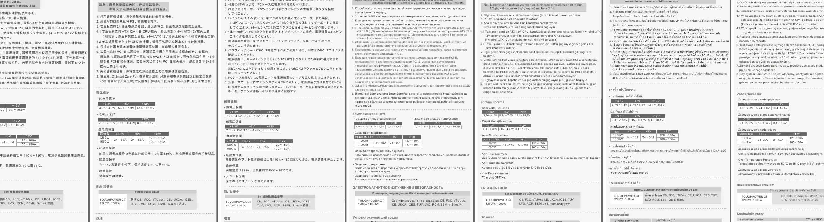
Technical Specifications
The TOUGHPOWER GT series includes built-in protection mechanisms, including Over Voltage Protection (OVP), Over Current Protection (OCP), Over Power Protection (OPP), Over Temperature Protection (OTP), and Short Circuit Protection (SCP). Operating temperature is 0°C to +40°C.
Manufacturer information
Thermaltake
Practical help
Common problems
Power supply does not turn on
Check AC power cord connection, ensure I/O switch is in 'I' position, verify all internal cable connections, and check if the UPS (if used) is powered on.
Before use
- Ensure the computer is powered off and unplugged.
- Verify the PSU is compatible with your system's power requirements.
- Use only genuine Thermaltake modular cables.
- Ensure all cables are securely plugged into both the PSU and the components.
- Do not open the PSU case.
Specs in practice
- PCI-E 6+2 pin
- Versatile connector for graphics cards; can be used as 6-pin or 8-pin by detaching the 2-pin section.
- ATX 12V 4+4 pin
- CPU power connector; can be split into a 4-pin connector if required by the motherboard.
Images and diagrams
- The manual provides a table detailing the exact quantity of each connector type (24-pin, ATX 12V, SATA, PCI-E, Peripheral) included for both the 1200W and 1000W models.
Model compatibility
- Third-party modular cables are not compatible and will void the warranty.

Manual page author
Michael Turner
Technical manual editor
Reviews PDF manuals for structure, safety notes, and practical product details so readers can find the right information quickly.