Automotive / Electrical Systems
Toyota 1GR-FE Generator Installation and Component Guide
A comprehensive technical guide for the Toyota 1GR-FE engine generator, featuring component diagrams, installation procedures, and critical torque specifications for assembly and maintenance.
Quick answers from the manual
Quick answer
- This manual provides the component breakdown, installation procedures, and torque specifications for the Toyota 1GR-FE engine generator. p. 1, 2, 3
Key actions
- Remove the V-Bank cover, battery tray, and engine under cover to access the generator. p. 1
- Disconnect the generator wire and connector before removing the generator mounting bolts. p. 2
Technical specifications
| Parameter | Value | Meaning | Pages |
|---|---|---|---|
| Generator Pulley Nut | 110 N·m | Specified torque for the pulley nut | p. 3 |
| Generator Mounting Bolt | 43 N·m | Specified torque for the main mounting bolt | p. 2 |
| Generator Wire Connection | 9.8 N·m | Specified torque for the wire connection | p. 2 |
Where to find it in the PDF
- Generator Components Overview p. 1
- Generator Installation and Wiring p. 2
- Generator Disassembly Exploded View p. 3
Table of contents
Manual images
Click an image to enlargeImportant Information
This document provides technical diagrams, assembly instructions, and torque specifications for the Toyota 1GR-FE engine generator. It is intended for service and maintenance purposes. Always ensure the battery is disconnected before performing any work on the charging system. Use the specified torque values provided in the diagrams to ensure proper assembly and prevent damage to components.
Generator Components
The generator system includes several external components that must be managed during service:
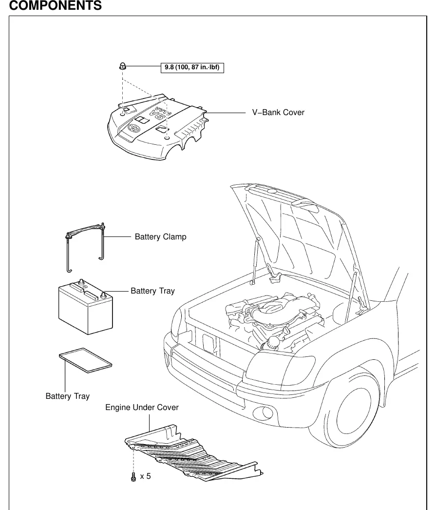
- V-Bank Cover: Must be removed to access the engine bay area.
- Battery Tray and Clamp: Must be removed to provide clearance.
- Engine Under Cover: Requires removal for access to lower components.
Installation and Removal
The generator is mounted to the engine and driven by the drive belt. Key steps for removal and installation include:
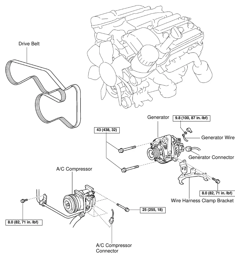
- Drive Belt: Must be removed to free the generator pulley.
- Wiring: Disconnect the generator wire and the generator connector before unbolting the unit.
- Mounting: The generator is secured with main mounting bolts. Ensure the wire harness clamp bracket is correctly positioned during reinstallation.
- A/C Compressor: The A/C compressor may need to be moved or disconnected to access the generator mounting bolts.
Generator Disassembly
The generator can be disassembled for internal component service. The exploded view details the following parts:
- Drive End Frame Assembly: Includes the generator pulley, retainer plate, and drive end frame bearing.
- Rotor Assembly: Includes the generator rotor, rotor bearing, and bearing cover.
- Rear End Assembly: Includes the brush holder assembly, plate seals, and rear end cover.
Torque Specifications
Proper torque is critical for the safe operation of the generator. Refer to the following key specifications:
- Generator Pulley Nut: 110 N·m (1,122 kgf·cm, 81 ft·lbf)
- Main Generator Mounting Bolt: 43 N·m (438 kgf·cm, 32 ft·lbf)
- A/C Compressor Mounting Bolt: 25 N·m (255 kgf·cm, 18 ft·lbf)
- Generator Wire Connection: 9.8 N·m (100 kgf·cm, 87 in·lbf)
- Wire Harness Clamp Bracket Bolt: 8.0 N·m (82 kgf·cm, 71 in·lbf)
Manufacturer information
Toyota Motor Corporation
Practical help
Before use
- Disconnect the battery negative terminal before starting work.
- Verify the condition of the drive belt before reinstallation.
- Ensure all electrical connectors are clean and free of corrosion.
- Use a torque wrench to tighten all bolts to the specified values.
- Check that the wire harness clamp bracket is properly secured.
Images and diagrams
- Page 1: Overview of external components to remove for generator access.
- Page 2: Generator mounting points, wiring connections, and A/C compressor interaction.
- Page 3: Exploded view of the generator internal components, including bearings and brush holder.
Model compatibility
- This guide is specific to the Toyota 1GR-FE engine generator.

Manual page author
Michael Turner
Technical manual editor
Reviews PDF manuals for structure, safety notes, and practical product details so readers can find the right information quickly.