Automotive / Towing Accessories
Installation Manual for Toyota / Suzuki 13-Pin Electric Wiring Kit
Comprehensive installation guide for the 13-pin electric wiring kit (Part No. 29500774) for Toyota and Suzuki vehicles. Includes safety instructions, trim removal steps, wiring diagrams, and troubleshooting procedures.
Table of contents
Manual images
Click an image to enlargeQuick guide from the manual
This document provides installation instructions for the 13-pin electric wiring kit designed for specific Toyota and Suzuki vehicles. Important: Installation must be performed by a professional workshop or a suitably qualified person. Failure to follow these instructions may void the warranty and damage the vehicle's electrical system.
- Safety First: Always disconnect the negative battery terminal before starting any work to prevent damage to the CAN data bus and control units.
- Troubleshooting: Limit troubleshooting to a maximum of 0.5 hours before contacting technical support.
- Compatibility: This kit is designed for specific models (e.g., eVitara, Urban Cruiser). Ensure your vehicle is compatible before installation.
Installation and Setup
The installation process involves removing interior trim panels, routing the wiring harness, and connecting to the vehicle's electrical system.
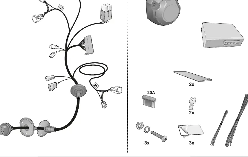
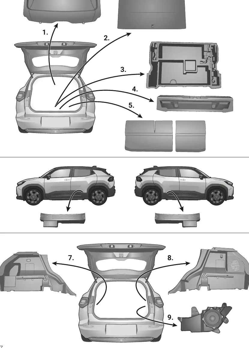
- Preparation: Disconnect the vehicle battery. Remove the necessary interior trim panels in the trunk area to access the wiring paths.
- Routing: Route the wiring harness from the trailer socket location into the vehicle interior.
- Connections: Connect the harness to the vehicle's CAN bus and electrical system as indicated in the diagrams. Ensure all connectors are fully seated.
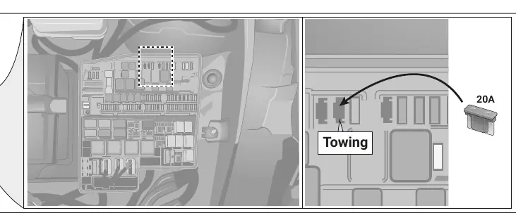
- Fuse Box: Locate the fuse box and insert the provided 20A fuse into the designated slot (marked 'Towing').
- Reassembly: Reinstall all trim panels once the electrical connections are verified.
Wiring and Socket Configuration
The kit uses the ISO 11446 standard for the 13-pin socket. Ensure all wires are connected according to the pin configuration:
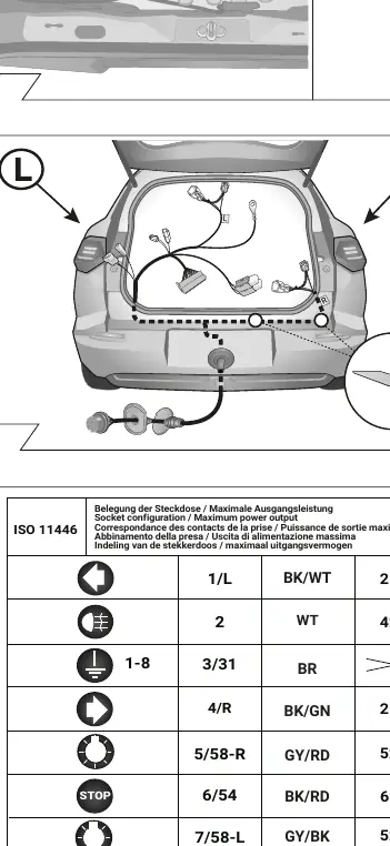
- 1/L: Left turn signal (BK/WT)
- 2: Fog light (WT)
- 3/31: Ground (BR)
- 4/R: Right turn signal (BK/GN)
- 5/58-R: Right tail light (GY/RD)
- 6/54: Stop light (BK/RD)
- 7/58-L: Left tail light (GY/BK)
- 8: Reversing light (BL/RD)
- 9: Permanent power (RD)
- 10: Charging wire (YL)
Troubleshooting and Diagnostics
The system includes diagnostic features to assist with installation and operation:
- Lamp Substitution: If a trailer indicator fails, the system automatically substitutes the corresponding rear light to flash at the correct frequency.
- LED Diagnosis: Use the control LEDs to verify the system status. If the system detects an error, check the connections and the fuse.
- Trailer Simulator: An optional trailer simulator can be used to test the 7-pin and 13-pin sockets.
Manufacturer information
Toyota Motor Corporation
Practical help
Common problems
Trailer indicators fail
The system automatically substitutes the rear light to flash at the correct frequency. Check the bulb if the error persists.
Malfunctions after installation
Limit troubleshooting to 0.5 hours and contact the hotline. Ensure the battery was disconnected during installation.
CAN bus errors
Ensure the negative battery terminal was disconnected before starting work. If not, the trailer module or vehicle control unit may be damaged.
Before use
- Read the entire manual before starting installation.
- Disconnect the negative battery terminal.
- Ensure the vehicle is compatible (eVitara/Urban Cruiser).
- Verify all electrical connections are secure.
- Check that the 20A fuse is correctly installed in the fuse box.
Images and diagrams
- Wiring diagram shows pin configuration for the 13-pin socket.
- Installation steps illustrate trim removal and cable routing paths.
Model compatibility
- Designed for Toyota and Suzuki vehicles (eVitara, Urban Cruiser).
- Trailer module is not diagnostic-capable.

Manual page author
David Miller
Documentation analyst
Organizes user manual content into clear summaries, with attention to model details, product context, and everyday usability.