Automotive / Electrical Systems
Toyota 1HZ, 1HDT Starter Contacts Kit Installation Guide
A comprehensive installation guide for the Toyota 1HZ and 1HDT engine starter contacts kit. Includes step-by-step removal, inspection, and installation procedures with torque specifications.
Quick answers from the manual
Quick answer
- This guide details the replacement of the magnetic switch terminal kit for Toyota 1HZ and 1HDT starters, including inspection limits, torque specifications, and assembly procedures. p. 1, 2, 3, 4
Key actions
- Inspect contact plate for wear (max 1.6 mm) p. 1
- Press contact plate with 981 N force before tightening p. 2
- Tighten terminal nuts to 36.3 N·m p. 3
Problems and fixes
Contact plate tilting
Ensure the contact plate is pressed down with the specified pressure before tightening the nut.
p. 3Technical specifications
| Parameter | Value | Meaning | Pages |
|---|---|---|---|
| Max wear | 1.6 mm | Replace if exceeded | p. 1 |
| Terminal nut torque | 36.3 N·m | Tightening torque for terminal nuts | p. 3 |
| End cover bolt torque | 3.6 N·m | Tightening torque for end cover bolts | p. 3 |
Where to find it in the PDF
- Removal and Inspection p. 1
- Installation and Pressing p. 2
- Torque and Reassembly p. 3, 4
Table of contents
Manual images
Click an image to enlargeImportant Information
This guide provides instructions for replacing the magnetic switch terminal kit on Toyota 1HZ and 1HDT starters. Always ensure you have the correct Special Service Tool (SST 09810-38140) before beginning. The contact plate must be inspected for wear; if the depth of wear exceeds 1.6 mm (0.063 in.), the contact plate must be replaced.
Removal of Magnetic Switch Terminal Kit
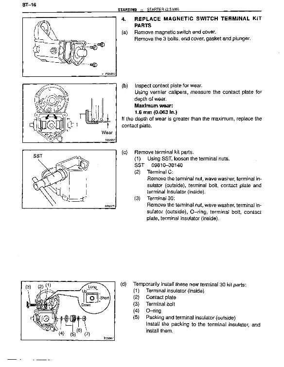
- Remove the magnetic switch and cover.
- Remove the 3 bolts, end cover, gasket, and plunger.
- Inspect the contact plate for wear using vernier calipers.
- Use SST 09810-38140 to loosen the terminal nuts.
- Remove the terminal kit parts, including the terminal nut, wave washer, terminal insulator (outside), terminal bolt, contact plate, and terminal insulator (inside) for both Terminal C and Terminal 30.
Installation of Terminal Kit

- Terminal 30 Kit: Temporarily install the terminal insulator (inside), contact plate, terminal bolt, O-ring, and packing with the terminal insulator (outside).
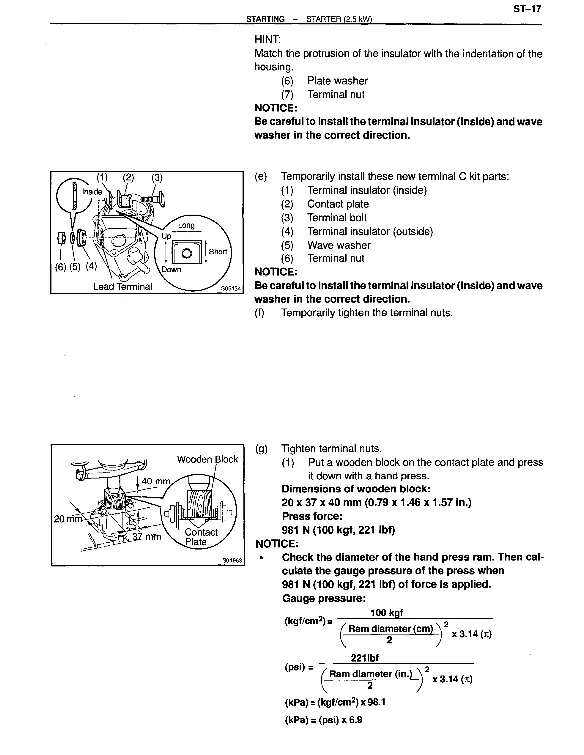
- Terminal C Kit: Temporarily install the terminal insulator (inside), contact plate, terminal bolt, terminal insulator (outside), wave washer, and terminal nut.
- Ensure the protrusion of the insulator matches the indentation of the housing.
- Tightening: Place a wooden block (20 x 37 x 40 mm) on the contact plate and press it down with a hand press using 981 N (100 kgf, 221 lbf) of force.
- Use SST 09810-38140 to tighten the nuts to the specified torque.
- Clean the contact surfaces of the contact plate and plunger with a dry shop rag.
- Reinstall the magnetic switch end cover, plunger, new gasket, and lead clamp with the 3 bolts.
Torque Specifications
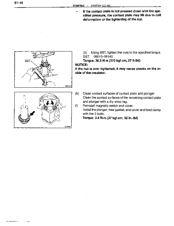
- Terminal Nuts: 36.3 N·m (370 kgf·cm, 27 ft·lbf)
- Magnetic Switch End Cover Bolts: 3.6 N·m (37 kgf·cm, 32 in·lbf)
Reassembly
Reassembly is performed in the reverse order of disassembly. Use high-temperature grease to lubricate the bearing and gears when assembling the starter.
Manufacturer information
Toyota Motor Corporation
Practical help
Common problems
Excessive contact plate wear
Measure with vernier calipers. If the depth of wear is greater than 1.6 mm (0.063 in.), the contact plate must be replaced.
Contact plate tilting during tightening
Ensure the contact plate is pressed down with the specified force (981 N) using a wooden block before tightening the nuts.
Insulator damage
Be careful to install the terminal insulator (inside) and wave washer in the correct direction. Do not overtighten the nuts, as this may cause cracks on the inside of the insulator.
Before use
- Verify availability of SST 09810-38140
- Prepare a wooden block (20 x 37 x 40 mm) for pressing the contact plate
- Ensure high-temperature grease is available for lubrication
- Have vernier calipers ready for wear inspection
- Ensure a dry shop rag is available for cleaning contact surfaces
Specs in practice
- Max wear limit
- 1.6 mm (0.063 in.) - replace if exceeded
- Terminal nut torque
- 36.3 N·m (370 kgf·cm, 27 ft·lbf)
- End cover bolt torque
- 3.6 N·m (37 kgf·cm, 32 in·lbf)
Images and diagrams
- The diagrams illustrate the removal sequence of the magnetic switch components.
- The diagrams show the correct orientation of the terminal insulators and washers.
- The diagrams demonstrate the use of the wooden block and hand press to secure the contact plate before tightening.
Model compatibility
- Applicable to Toyota 1HZ and 1HDT engine starters.

Manual page author
Michael Turner
Technical manual editor
Reviews PDF manuals for structure, safety notes, and practical product details so readers can find the right information quickly.