Automotive / Parts & Accessories
Toyota Electronically Controlled Transmission Service Manual
Comprehensive service manual and wiring diagrams for the Toyota Electronically Controlled Transmission. Includes system operation, diagnostic voltage values, and connector locations.
Table of contents
Manual images
Click an image to enlargeQuick guide from the manual
This document provides essential wiring diagrams, system operation outlines, and diagnostic service hints for the Toyota Electronically Controlled Transmission. It is intended for technicians to troubleshoot electrical issues, verify sensor signals, and locate connectors within the vehicle harness.
- System Operation: Understand how the Engine Control Module (ECM) manages gear shifts, lock-up, and overdrive.
- Diagnostics: Use the provided voltage and resistance values to test solenoids, switches, and sensors.
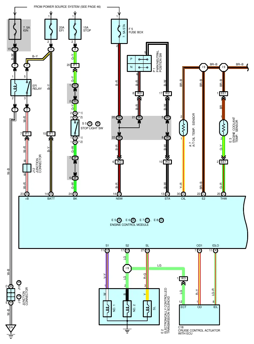
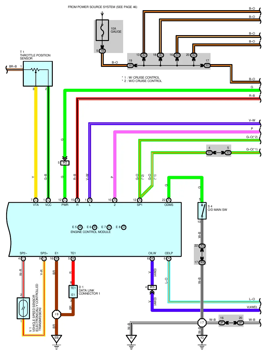
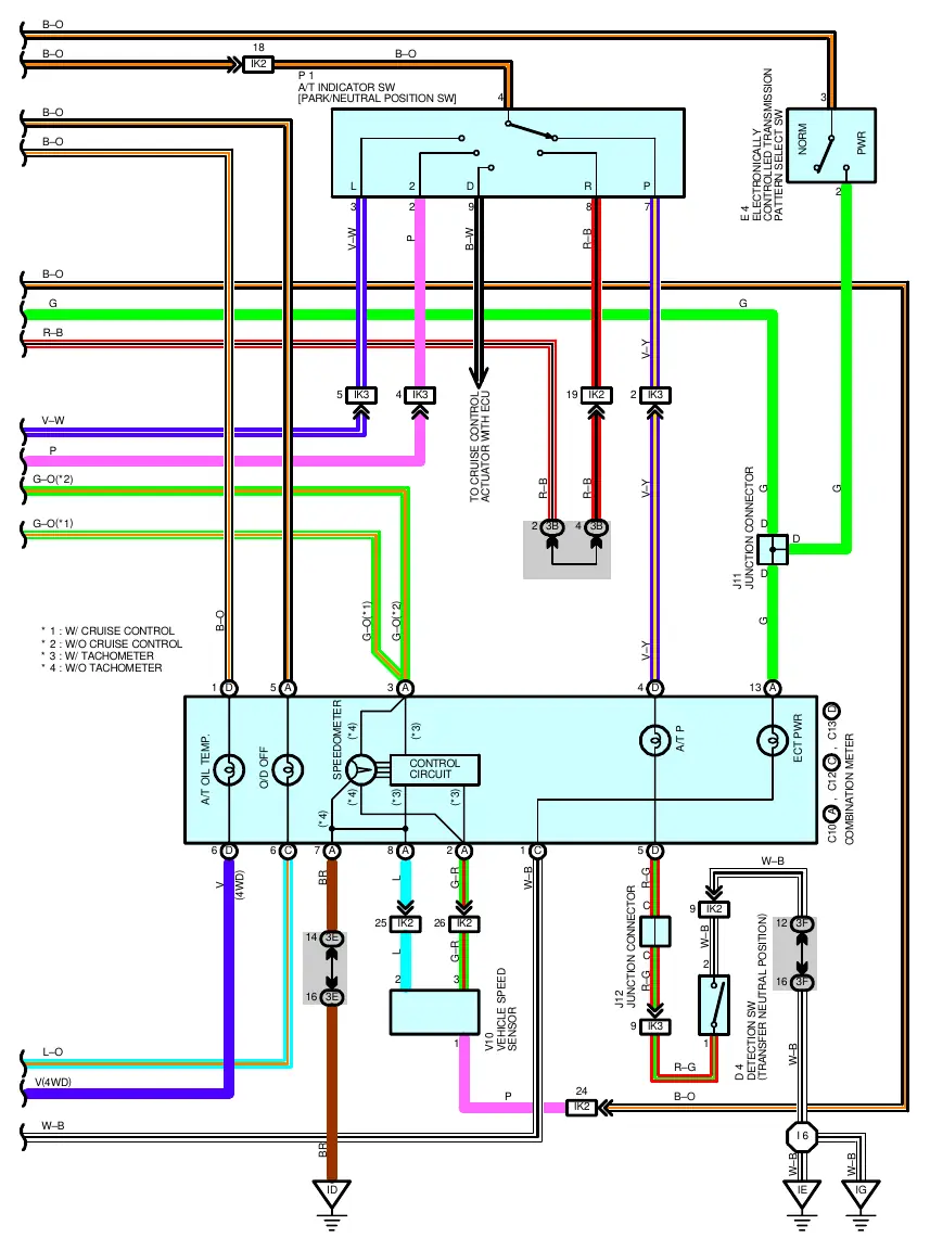
- Wiring Diagrams: Refer to the schematics for signal paths between the ECM and transmission components.
System Outline
The electronically controlled transmission uses the engine control module to manage gear shifts based on input signals from various sensors. Key functions include:
- Gear Shift Operation: The ECM selects the appropriate gear based on engine coolant temperature and vehicle speed signals. Current is output to solenoids to engage specific gears.
- Lock-up Operation: When conditions are met, the ECM activates the lock-up solenoid to improve efficiency.
- Stop Light Switch Circuit: Depressing the brake pedal sends a signal to the ECM to cut continuity to the lock-up solenoid.
- Overdrive Circuit: The O/D main switch allows the driver to enable or disable overdrive. The ECM monitors this switch to control shifting.
- A/T Oil Temp Warning: If fluid temperature exceeds 150°C (302°F), the ECM activates a warning light. The light turns off once the temperature drops to 120°C (248°F) or less.
Service Hints and Diagnostics
Use these values to verify component health using a multimeter:
- Transmission Solenoid: Resistance should be approximately 13 Ohm.
- Park/Neutral Position Switch: Should show approximately 12 volts with the ignition switch in the ACC position.
- Engine Control Module (ECM) Terminals:
- S1-E1: 9-14 volts.
- S2, SL-E1: 0-1.5 volts.
- THW-E2: 0.2-1.0 volts (at 80°C coolant temp).
- VTA-E2: 0.3-0.8 volts (throttle fully closed) to 3.2-4.9 volts (throttle fully open).
- +B/BATT-E1: 9-14 volts.
Parts and Connector Locations
The manual includes detailed tables for locating parts, relay blocks, and ground points. Refer to the specific pages listed in the parts location table to find the physical location of connectors (e.g., J12, E4) and ground points (e.g., EA, EB) within the vehicle.
Manufacturer information
Toyota Motor Corporation
Practical help
Common problems
Transmission not shifting gears correctly
Check continuity to the No.1 and No.2 solenoids. Verify ECM output signals at terminals S1 and S2.
Overdrive not engaging
Check the O/D main switch signal at terminal ODMS. It should be 9-14V when ON and 0V when OFF.
A/T Oil Temp warning light stays on
Verify fluid temperature. If below 120°C, check the sensor circuit and ECM terminal OILW.
Before use
- Ensure the ignition switch is in the correct position (ACC or ON) as specified for the test.
- Verify the brake pedal status when testing the Stop Light Switch circuit.
- Use a multimeter to check voltage at the specified ECM terminals.
- Check fluid temperature before diagnosing A/T Oil Temp warning issues.
- Identify the correct wiring diagram page based on the specific engine model (e.g., 5VZ-FE).
Specs in practice
- Solenoid Resistance
- Approx. 13 Ohm (measured to ground).
- P/N Switch Voltage
- Approx. 12V with ignition in ACC position.
- A/T Oil Temp Warning
- Activates at 150°C (302°F) or higher; deactivates at 120°C (248°F) or lower.
Images and diagrams
- Wiring diagrams illustrate the electrical path between the Engine Control Module (ECM) and transmission components.
- Connector codes (e.g., IK3, 3E) indicate specific wiring harness junctions.
- Ground points (e.g., EA, EB) are critical for completing the electrical circuit.
Model compatibility
- Specific wiring diagrams are provided for the 5VZ-FE engine (excluding California models).

Manual page author
David Miller
Documentation analyst
Organizes user manual content into clear summaries, with attention to model details, product context, and everyday usability.