Lighting / Controllers & Dimmers
User Manual for Tridonic smartSWITCH HF 12DP MB f and HF 12DP MB S f Motion Detector
Quick guide for the Tridonic smartSWITCH HF 12DP MB f and HF 12DP MB S f motion detector. Includes installation instructions, wiring diagrams, sensor settings, and technical specifications.
Table of contents
Quick guide from the manual
The Tridonic smartSWITCH HF 12DP MB f and S f are motion detectors designed for installation inside luminaires. They feature adjustable detection areas, switch-off delays, and daylight thresholds. The device is suitable for indoor use in areas like corridors and closed parking garages. Note that the sensor must be installed in non-metallic housings (e.g., plastic or glass) to function correctly.
Installation
Important: The power supply must be disconnected before installation. The device must be installed by qualified personnel only.
- Housing: Use only non-metallic housing materials (plastic or glass). Metal housings will block the sensor.
- Positioning: The sensor must protrude over the light sources.
- Environment: Suitable for indoor luminaires without vibrations.
- Compatibility: Do not use with phase cut dimmers.
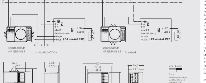
- Wiring: Refer to the wiring diagram provided in the manual for correct connection to the control gear (LCA one4all PRE).
Setting up the sensor
The sensor settings are configured using DIP switches located on the device. Refer to the tables in the manual for specific switch positions:
- Sensitivity: Adjusts the detection range (100% to 10%).
- Hold time: Sets the switch-off delay after the last motion is detected (5s to 30min).
- Daylight threshold: Prevents the light from switching on when there is sufficient ambient light (Disable to 2 Lux).
corridorFUNCTION
The corridorFUNCTION can be activated by applying 230 V for 5 minutes at the switchDIM connection of the control gear or via the corridorFUNCTION Plug. To ensure the sensor switches on in conjunction with this function, set the daylight threshold to 'Disable'.
Technical data
- Rated supply voltage: 220–240 V, 50 Hz
- Frequency: 5.8 GHz
- Load: 800 W (resistive), 400 VA (capacitive)
- Detection angle: 30–150°
- Max. mounting height: 12 m
- Protection: IP20
- Ambient temperature: -20 to +70 °C
Safety instructions
- The device must only be used for the specified applications.
- Observe all relevant safety and accident prevention regulations.
- Installation must be performed by specialist staff.
Manufacturer information
Tridonic
Practical help
Common problems
Sensor does not switch on with corridorFUNCTION
Set the daylight threshold value to I = Disable.
Light switches on/off unnecessarily
Reduce the detection area or increase the switch-off delay (hold time).
Motion not detected
Ensure the housing material is thin (plastic or glass) and not metal. Check that the sensor is not obstructed.
Before use
- Disconnect the power supply before starting installation.
- Verify the luminaire housing is non-metallic (plastic or glass).
- Ensure the sensor is positioned to protrude over the light sources.
- Confirm the installation environment is free from vibrations.
- Check that no phase cut dimmers are used in the circuit.
Specs in practice
- Detection angle (30–150°)
- The field of view of the motion sensor; can be restricted by housing.
- Hold time (5s – 30min)
- The duration the light stays on after the last detected motion.
- Daylight threshold (Disable – 2 Lux)
- The ambient light level below which the sensor will trigger the light.
Images and diagrams
- Wiring diagram: Shows connections for standard and corridorFUNCTION setups using the LCA one4all PRE control gear.
- Mounting diagram: Illustrates ceiling and wall mounting configurations with detection range 'd' and height 'h'.
Model compatibility
- Not compatible with phase cut dimmers.
- Only for indoor use (e.g., corridors, closed parking garages).
- Requires non-metallic housing for RF signal penetration.

Manual page author
David Miller
Documentation analyst
Organizes user manual content into clear summaries, with attention to model details, product context, and everyday usability.