Lighting / LED Drivers
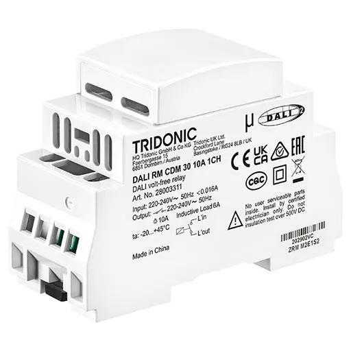
DALI-2 1-Channel Relay Tridonic DALI RM CDM 30 10A 1CH
Quick guide for the Tridonic DALI RM CDM 30 10A 1CH DALI-2 1-channel relay. Includes installation instructions, wiring diagrams, technical specifications, and safety precautions.
Table of contents
Manual images
Click an image to enlargeQuick guide from the manual
The Tridonic DALI RM CDM 30 10A 1CH is a DALI-2 compliant 1-channel relay designed for switching loads. It is suitable for mounting on a 35 mm DIN rail and is optimized for electronic loads with high inrush currents, such as LED drivers.
Product Description
- DALI-2 relay compatible with DALI and DALI-2 systems.
- 1-channel actuator with DALI-2 input.
- Potential-free relay contact.
- Optimized for high inrush currents up to 490 A / 1.5 ms.
Installation
Installation must be performed by qualified personnel only. Ensure the power supply is disconnected before starting work.

- Mount the device on a 35 mm DIN rail.
- Use solid or stranded wire with wire end ferrules, cross-section 1 to 4 mm².
- Strip wire insulation by 6–7 mm.
- To remove from the DIN rail, use a flat-head screwdriver to release the locking lever.
Wiring
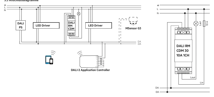
Connect the mains supply (L, N) and the load according to the provided wiring diagrams. The device supports switching of loads that do not have a DALI input.
Safety and Technical Data
Important: Do not connect the device to DC (direct current). Protect the secondary side with a circuit breaker or FI-switch with a nominal value not exceeding 10 A to prevent damage in case of a short circuit.
- Mains voltage: 220–240 V, 50/60 Hz.
- Output load: 10 A (resistive) / 6 A (inductive).
- Protection class: IP20, Class II.
- Ambient temperature: -20 to +45 °C.
Manufacturer information
Tridonic
Practical help
Common problems
Short circuit on secondary side
Use a circuit breaker or FI-switch with a nominal value not higher than 10 A.
Device damage
Do not connect to DC (direct current).
Removal from DIN rail
Use a flat-head screwdriver to release the locking lever.
Before use
- Ensure power is disconnected
- Verify load type (resistive/inductive)
- Use 35 mm DIN rail
- Prepare wires (1-4 mm² cross-section)
Specs in practice
- 490 A / 1.5 ms
- Maximum inrush current capacity.
Images and diagrams
- Wiring diagram shows connection of DALI bus, mains power (L/N), and switched load.
- Installation diagram illustrates mounting on DIN rail and removal using a screwdriver.
Model compatibility
- Compatible with DALI and DALI-2 systems.
- DALI is not SELV; follow low-voltage installation regulations.

Manual page author
David Miller
Documentation analyst
Organizes user manual content into clear summaries, with attention to model details, product context, and everyday usability.