Lighting / LED Drivers
User Manual for Tridonic Driver LC 10W 350mA fixC Ip SNC2
Quick guide for the Tridonic Driver LC 10W 350mA fixC Ip SNC2. Includes installation instructions, wiring guidelines, technical specifications, and safety features.
Table of contents
Manual images
Click an image to enlargeQuick guide from the manual
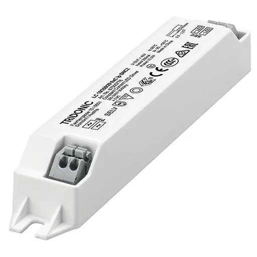
The Tridonic Driver LC 10W 350mA fixC Ip SNC2 is a constant current LED driver designed for built-in use within luminaires. It features overload, short-circuit, and no-load protection. Installation requires adherence to specific wiring guidelines to ensure electromagnetic compatibility and safety. The device is intended for luminaires of protection class I and II.
Installation and wiring
The driver uses push-wire terminals (WAGO 250) for connections. Follow these steps for proper wiring:
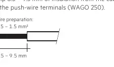
- Wire type: Use stranded wires with ferrules or rigid wires with a cross-section of 0.5 – 1.5 mm².
- Preparation: Strip 8.5 – 9.5 mm of insulation from the cables.
- Connection: Insert wires into the push-wire terminals.
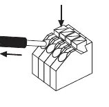
- Release: To remove a wire, press down the push button and pull the cable from the front.
Wiring guidelines:
- Keep all connections as short as possible to ensure good EMI behavior.
- Maintain a distance of 5 – 10 cm between mains leads and the LED driver/other leads.
- The maximum length of output wires is 2 m.
- Protect wiring against short circuits to earth (e.g., sharp-edged metal parts).
Replacing LED module
- Switch off the mains power.
- Remove the existing LED module.
- Wait for 30 seconds.
- Connect the new LED module.
Note: Hot plug-in or output switching of LEDs is not permitted and may cause very high current to the LEDs.
Technical specifications
- Output current: 350 mA
- Max. output power: 10.2 W
- Input voltage: 220 – 240 V (AC voltage range 198 – 264 V)
- Protection: IP20
- Ambient temperature (ta): -20 to +50 °C
- Lifetime: Up to 50,000 hours
Safety and protection
The driver includes built-in protection mechanisms:
- Overload protection: If the maximum load is exceeded, the driver protects itself (LED may flicker). Nominal operation is restored automatically after the overload is removed.
- Short-circuit protection: The driver switches off in case of a short circuit on the secondary side and recovers automatically after the fault is eliminated.
- No-load protection: Operates in burst mode to provide constant output voltage regulation if the LED string opens.
Manufacturer information
Tridonic
Practical help
Common problems
LED flickering
Check if the maximum load is exceeded. The driver will protect itself and restore operation automatically once the overload is removed.
Driver not working
Check for a short circuit on the secondary side. The driver will switch off and recover automatically after the fault is eliminated.
EMI or interference issues
Ensure connections are as short as possible and keep mains leads separated from LED leads by 5-10 cm.
Before use
- Verify input voltage is 220-240V.
- Ensure wire cross-section is 0.5-1.5 mm².
- Strip insulation 8.5-9.5 mm.
- Ensure luminaire is protection class I or II.
- Check that output wires do not exceed 2 m in length.
Specs in practice
- Output current
- 350 mA constant current output.
- Max. output power 10.2 W
- The maximum power the driver can supply to the LED load.
Images and diagrams
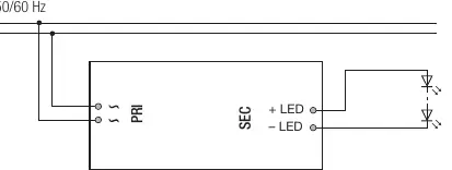
- Circuit diagram shows PRI (mains) and SEC (LED) connections.
- Wiring diagram illustrates push-wire terminal usage.
- Wiring release diagram shows how to use the push button to remove wires.
Model compatibility
- Designed for luminaires of protection class I and II.
- Inbuilt LED controlgear intended for use within a luminaire enclosure.

Manual page author
Michael Turner
Technical manual editor
Reviews PDF manuals for structure, safety notes, and practical product details so readers can find the right information quickly.