Automotive / Garage Equipment
User Manual for VEVOR 1500LBS Motorcycle Lift ZX0901-3C
Quick guide for the VEVOR 1500LBS Motorcycle Lift (Model ZX0901-3C). Learn how to safely operate, lift, lower, and maintain your hydraulic motorcycle lift.
Table of contents
Manual images
Click an image to enlargeQuick Guide
This manual provides instructions for the VEVOR 1500LBS Motorcycle Lift (Model ZX0901-3C). This device is designed for lifting motorcycles and ATVs for cleaning and servicing. Always operate on a hard, level surface and never exceed the 1500 lb. rated capacity. Ensure the mechanical load holding means (stop bars) are engaged before working on the vehicle.
Safety Instructions
- Capacity: Do not exceed 1500 lb. rated capacity.
- Surface: Use only on hard, level surfaces.
- Support: This is a lifting device only. Immediately after lifting, support the vehicle with appropriate means.
- Operation: Keep clear of the load while lifting and lowering. Lower the load slowly.
- Safety Gear: Wear ANSI-approved safety goggles and heavy-duty work gloves.
- Inspection: Inspect before every use; do not use if parts are loose or damaged.
- Restraint: Secure the load with an appropriate restraint device.
- Locking: Immediately after lifting, ensure the mechanical load holding means is engaged.
- Prohibitions: Do not use for aircraft purposes. Do not move or dolly the vehicle while on the lift. Do not allow anyone to ride the lift.
Specifications
- Model: ZX0901-3C
- Capacity: 1500 lbs
- Min Height: 120 mm
- Max Height: 385 mm
- Gross Weight: 29.6 kg
- Net Weight: 27.6 kg
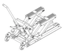
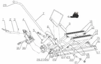
Main Construction
The lift consists of several key components, including the lifting arm, pump, release pedal, foot pedal, and safety stop bars. Refer to the exploded view diagram for the assembly of parts such as the rubber pads, caster wheels, and hinge pins.
Operation
Lifting
- Lift the Stop Bar Connecting Rod and secure it to the Stop Bar Rod Clamp.
- Use the handle to position the lift under the load. Lower the lift by depressing the Release Pedal.
- Turn the Lock Bolts until they contact the ground and lift the rear wheels slightly off the ground to prevent rolling.
- Use tie-down straps to secure the load.
- Repeatedly depress the Foot Pedal slowly to raise the lift. Ensure the load sits evenly on the Lift Saddle.
- Continue to raise to the desired height. Disengage the Stop Bar Connecting Rod from the clamp.
- Lock the lift at one of the three locking positions on the bottom base using the Stop Bars and lower the lift slightly to engage them.
Lowering
- Depress the foot pedal slowly to raise the lift enough to disengage the stop bars.
- Lift up the stop bar connecting rod and secure it to the stop bar rod clamp.
- Press the release pedal slowly and gently lower the load. Never allow the load to come down quickly.
- Once the load is on the ground, remove the tie-down straps.
- Turn the Lock Bolts until they are clear of the ground, allowing the rear wheels to contact the ground. Roll the lift out.
Maintenance
- Inspection: Before each use, inspect for broken, cracked, or bent parts. Do not use damaged equipment.
- Testing: Thoroughly test the lift for proper operation before actual use.
- Hydraulic Oil: Change the hydraulic oil at least once every three years.
- Oil Change Procedure: With the lift fully lowered, remove the Oil Filler Plug on the side of the Bottle Jack. Drain the old oil by placing the lift on its side. Refill with high-quality hydraulic oil until it begins to run out of the fill hole. Reinstall the plug.
- Storage: Wipe dry with a clean cloth and store in a safe, dry location out of reach of children.
Manufacturer information
VEVOR
Practical help
Common problems
Lift rolls while in use
Turn the Lock Bolts until they contact the ground and lift the rear wheels slightly off the ground.
Load is unstable
Ensure the load is distributed evenly on the two Rubber Pads and secured with tie-down straps.
Lift will not hold height
Ensure the mechanical load holding means (Stop Bars) are properly engaged in one of the three locking positions.
Before use
- Inspect for broken, cracked, or bent parts.
- Check for loose or missing hardware.
- Ensure the surface is hard and level.
- Verify the load does not exceed 1500 lbs.
- Test the lift for proper operation.
Images and diagrams
- The exploded view shows the assembly of the lifting arm, pump, and base components.
- Stop bars are located on the bottom base to lock the lift at different heights.
Model compatibility
- Designed for motorcycles and ATVs.
- Not for aircraft purposes.

Manual page author
Emily Carter
User documentation editor
Prepares concise manual descriptions and highlights the most useful setup, operation, and maintenance information for readers.