Automotive / Garage Equipment
User Manual for AGT Industrial 1500LBS Motorcycle Lift
Quick guide for the AGT Industrial 1500LBS Motorcycle Lift. Includes safety instructions, operation steps for lifting and lowering, maintenance procedures, and technical specifications.
Table of contents
Manual images
Click an image to enlargeQuick guide from the manual
This manual provides instructions for the AGT Industrial 1500LBS Motorcycle Lift. Key operational requirements include using the lift only on hard, level surfaces, never exceeding the 1500 lb capacity, and always engaging the mechanical stop bars before working on the vehicle.
Main specifications
- Capacity: 1500 lbs
- Minimum height: 120 mm
- Maximum height: 380 mm
- Gross Weight: 30 kg
- Net Weight: 28 kg
- Packing size: 850 x 400 x 150 mm
Safety instructions
Always follow these safety guidelines to prevent injury:
- Do not exceed the rated capacity of 1500 lbs.
- Use only on hard, level surfaces.
- Always secure the load with tie-down straps.
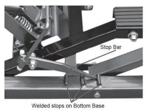
- Ensure the mechanical load holding means (Stop Bars) is engaged after lifting.
- Never move or dolly the vehicle while it is on the lift.
- Wear ANSI-approved safety goggles and heavy-duty work gloves.
- Never allow anyone to ride the lift while it is being raised or lowered.
Operation
Lifting
- Lift the Stop Bar Connecting Rod and secure it to the Stop Bar Rod Clamp.
- Position the lift under the load using the handle.
- Lower the lift by depressing the Release Pedal.
- Turn the Lock Bolts until they contact the ground to prevent rolling.
- Secure the load with tie-down straps.
- Depress the Foot Pedal to raise the lift.
- Once at the desired height, disengage the Stop Bar Connecting Rod and lock the lift at one of the three locking positions on the bottom base.
Lowering
- Remove all tools and parts from under the lift.
- Depress the Foot Pedal slightly to raise the lift and disengage the Stop Bars.
- Lift the Stop Bar Connecting Rod and secure it to the clamp.
- Press the Release Pedal slowly to lower the load.
- Once on the ground, remove straps, turn Lock Bolts to clear the ground, and roll the lift away.
Maintenance
Perform the following maintenance to ensure longevity:
- Inspect the lift before every use for broken, cracked, or bent parts.
- Do not use damaged equipment.
- Change the hydraulic oil at least once every three years. To do this, remove the Oil Filler Plug on the side of the Bottle Jack, drain the old oil, and refill with high-quality hydraulic oil.
Practical help
Common problems
Lift won't hold load at height
Ensure the mechanical load holding means (Stop Bars) is fully engaged in one of the locking positions.
Lift rolls while in use
Turn the Lock Bolts until they contact the ground and lift the rear wheels slightly off the ground.
Load unstable on lift
Ensure the load is evenly distributed on the two Rubber Pads and secured with tie-down straps.
Before use
- Inspect for broken, cracked, or bent parts.
- Check for loose or missing hardware.
- Ensure the surface is hard and level.
- Verify the load does not exceed 1500 lbs.
- Test the lift for proper operation before actual use.
Images and diagrams
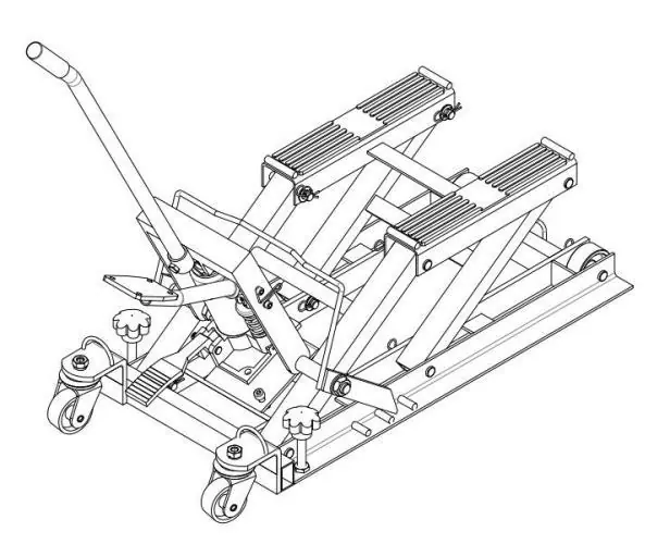
- Parts 1-31 identify components like rubber pads, foot pedal, handle, and wheels.
- Stop Bars (Part 24) are critical for locking the lift at height.
Model compatibility
- Designed for motorcycles and ATVs.
- Not for aircraft purposes.

Manual page author
David Miller
Documentation analyst
Organizes user manual content into clear summaries, with attention to model details, product context, and everyday usability.