Home Appliances / Commercial Kitchen Equipment
Vulcan 00-913102-0176A Steamer Replacement Timer Kit Installation Instructions
Installation guide for the Vulcan 00-913102-0176A Steamer Replacement Timer Kit. Includes wiring diagrams, step-by-step replacement procedures, and safety precautions for various commercial steamer models.
Table of contents
Manual images
Click an image to enlargeImportant Information
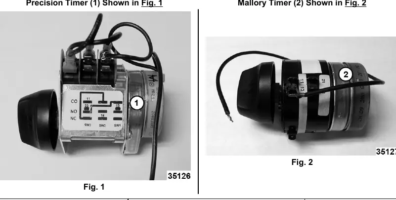
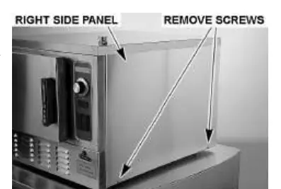
This document provides installation instructions for the Vulcan Steamer Replacement Timer Kit (Part # 00-913102-0176A). The kit contains either a Mallory or Precision timer; both are compatible with all supported models, though wiring may differ slightly. Always refer to the specific wiring diagram for your steamer model.
Safety Precautions
- Disconnect all electrical power to the machine before starting work.
- Follow established lockout/tagout procedures to prevent accidental power restoration.
- Handle the new timer with care; do not touch cams or switch levers with hands or tools.
- Do not remove any jumper wires on the Precision brand timer.
Installation Procedure
Removing the Old Timer
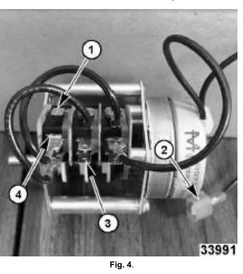
- Remove the right side panel by removing the screws from the bottom of the panel.
- Pull the bottom of the panel out and slide it down to clear the top cover.
- Note the existing wiring configuration and disconnect the old timer.
Installing the New Timer
- Connect the new timer wiring according to the specific model instructions provided in this manual.
- Verify the orientation nub on the front face of the timer engages the small hole on the back side of the steamer front panel.
- Secure the shaft to the steamer panel using the new seal nut included in the kit.
- Torque the seal nut up to, but not over 15 in. lbs.
- Install the right side panel.
- Restore power to the steamer.
Testing
- Turn the steamer on.
- Set the timer to 5 minutes when the steamer is ready to cook.
- Verify that the alarm sounds and the cook light goes out simultaneously or near 0 minutes.
Wiring and Compatibility
The manual includes specific wiring instructions for the following models:
- C24EA6/10 and C24GA6/10
- C24EA3/5, HC24EA3/5, C24EO3/5, and HC24EO3/5
Note: On the Precision Timer with exposed micro switches, the wire on terminal #21 is not used and must be taped off and insulated.
Practical help
Common problems
Timer not engaging with the panel
Verify the orientation nub on the front face of the timer engages the small hole on the back side of the steamer front panel.
Seal nut overtightened
Torque the seal nut up to, but not over 15 in. lbs. to avoid damage.
Unused wire on Precision Timer
The wire on terminal #21 is not used on the Precision Timer with exposed micro switches; it must be taped off and insulated.
Before use
- Disconnect electrical power to the machine.
- Follow lockout/tagout procedures.
- Identify if you have a Mallory or Precision timer.
- Locate the wiring diagram corresponding to your specific steamer model.
- Ensure the orientation nub is aligned during installation.
Specs in practice
- Seal Nut Torque
- Maximum 15 in. lbs. Do not exceed this to prevent damage to the shaft or panel.
Images and diagrams
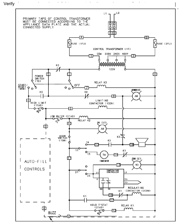
- Wiring diagrams are provided for specific models (C24EA, C24GA, C24EO, C24DA, C24ET). Ensure you use the diagram corresponding to your specific steamer model.
- Figures 1 and 2 identify the two types of timers (Mallory vs. Precision) included in the kit.
Model compatibility
- Kit includes either Mallory or Precision Timer; both work on all models but have slight wiring differences.
- PRO model steamers require only one terminal connection for wire #14.

Manual page author
Emily Carter
User documentation editor
Prepares concise manual descriptions and highlights the most useful setup, operation, and maintenance information for readers.