Home Appliances / Commercial Kitchen Equipment
Operation, Installation & Maintenance Manual for Cleveland Electric Mixer Kettles
Comprehensive operation, installation, and maintenance guide for Cleveland Electric Mixer Kettles. Includes troubleshooting, safety procedures, calibration, and cleaning instructions.
Table of contents
Manual images
Click an image to enlargeQuick Guide from the Manual
This manual provides essential instructions for the safe operation, installation, and maintenance of Cleveland Electric Mixer Kettles. Operators must perform a daily pre-startup inspection, including checking that the kettle tilts smoothly, the pressure gauge is in the green zone, and the green light illuminates when energized. Always ensure the unit is installed under a ventilation hood and that the electrical supply matches the rating label.
Installation
Installation must be performed by qualified personnel in accordance with local codes. Positioning: Ensure the unit is level by adjusting the flanges on the feet. Electrical: Connect permanent copper wiring to the junction box in the console. The unit is not GFI (GFCI) compatible. Ventilation: Proper ventilation is required to manage steam and humidity buildup. Installation Checks: Verify motor rotation, test the mixer bridge movement, and check for leaks in water faucets and discharge valves.
Operating Instructions
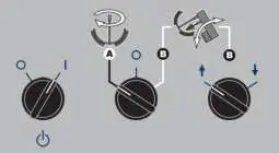
Controls: The control panel includes a main power switch, mix/lift switch, up/down switch, mixer speed control, and emergency stop button. Operation: Turn on the main power switch and set the steam control valve. To lift or lower the bridge, use the mix/lift switch and up/down switch. To mix, set the mix/lift switch to 'mix' and adjust the speed control. Tilting: Use the handwheel or power tilt control switch to tilt the kettle. Do not tilt the kettle when mixer agitators are in the bowl.
Cleaning and Maintenance
Cleaning: Clean the unit shortly after each use. Use warm water and mild detergent with a nylon brush. Do not use harsh detergents, chloride-based cleaners, or high-pressure spray hoses. Preventative Maintenance: Perform daily inspections, six-month service inspections (grease bearings, check gears), and yearly inspections (replace hydraulic oil and filter, calibrate temperature).
Troubleshooting
If the kettle is not heating, check for incoming power, ensure it is not tilted, and verify the low water condition. If the kettle heats too slowly, check for air in the jacket (venting required) or defective components like the thermostat or potentiometer. If the red low water light remains on, check the low water level probe.
Calibration
To calibrate, ensure the kettle is empty and has a vacuum. Heat to maximum temperature (266°F/130°C) and allow the unit to cycle twice. Check the surface temperature with a digital thermometer; it should be between 260°F and 265°F. Adjust the potentiometer on the black box as needed.
Practical help
Common problems
Kettle is not heating
Check for incoming power, ensure kettle is not tilted, verify low water condition, or check for defective safety thermostat, contactors, or thermistor.
Kettle heats too slowly or not hot enough
Check for air in the jacket (perform venting procedure), or check for defective potentiometer, thermistor, or contactors.
Kettle is overheating
Check for defective thermistor, potentiometer, 12 VDC relay, or control box.
Red LED remains illuminated even after adding water
Check for a defective low water level probe or control box.
Before use
- Ensure the unit is clean and sanitized.
- Check that the pressure gauge is in the green zone.
- Verify the main power supply is connected and correct.
- Ensure the kettle is in the upright position.
- Check for any hydraulic leaks.
- Ensure adequate ventilation is provided.
Specs in practice
- Ambient Temperature
- Recommended operating range is 13°C to 39°C (55°F to 102°F).
- Relative Humidity
- Designed for 40% to 65% humidity; exceeding 65% may compromise electrical components.
- Water Inlet Pressure
- Operating range is 275 Kpa to 1Mpa.
Images and diagrams
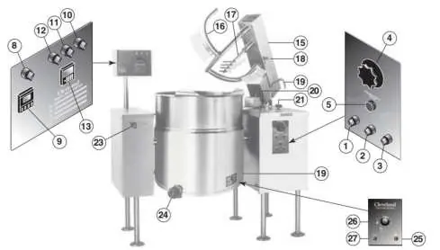
- Controls and Indicators: Identifies 27 numbered components including switches, valves, and gauges.
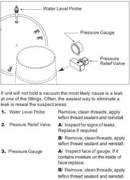
- Diagnostic Guide: Step-by-step fault isolation for heating and water level issues.
- Hinge Adjustment: Shows Allen wrench usage for spring tension.
Model compatibility
- Not GFI (GFCI) compatible.
- Not for making dough or heavy dough-like products.

Manual page author
David Miller
Documentation analyst
Organizes user manual content into clear summaries, with attention to model details, product context, and everyday usability.