Home Appliances / Commercial Kitchen Equipment
User Manual for Vulcan 1024, 1036, and 1048 Series Commercial Electric Cheesemelter
Quick guide for the Vulcan 1024, 1036, and 1048 series commercial electric cheesemelters. Includes installation, wall mounting, heater and rack setup, operation, and troubleshooting.
Table of contents
Manual images
Click an image to enlargeQuick Guide from the Manual
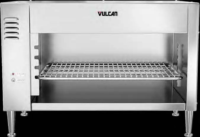
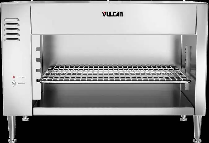
This manual covers the installation and operation of Vulcan commercial cheesemelters (models 1024, 1036, and 1048). These units are designed for countertop or wall-mounted use to finish, glaze, or keep food warm. Key operational requirements include ensuring the unit is level, properly connected to a 208V or 240V single-phase power supply, and that the rack is correctly positioned to trigger the automatic heating switch.
Installation
Unpacking: Inspect the unit immediately upon receipt. If damaged, notify the carrier within 5 business days and keep all original packing materials. Do not move, install, or modify a damaged unit.
Location: Ensure the unit is level side-to-side and front-to-back. Do not install pass-through models on a wall. It is recommended to avoid installing the unit directly over or adjacent to charbroilers, griddles, or fryers, as grease-laden smoke can shorten the life of the quartz heating elements.
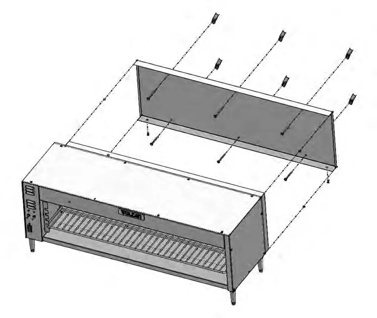
Wall Mounting (Models 1024, 1036, 1048W only):
- Remove the two back retaining bolts at the bottom rear of the unit.
- Pry out the back panel and remove it by pulling out and down.
- Remove and save the insulation.
- Use the back panel as a template to mark and drill holes for wall mounting.
- Fasten the back panel to the wall using lag bolts or anchors (not provided). Ensure it is level.
- Replace the insulation and hang the cheesemelter onto the mounted back panel.
- Secure the unit by replacing the two back retaining bolts.
Setup
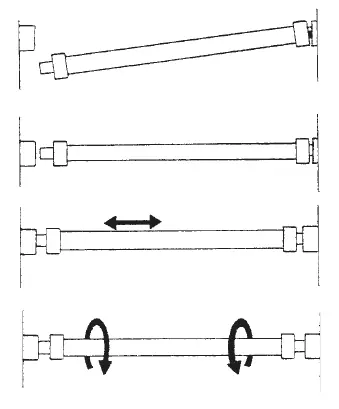
Heater Installation: Push one end of the heater into a socket as far as it will go. Swing the other end up until it aligns with the opposite socket and release it to snap into place. Move the heater back and forth to ensure it is centered, then rotate it clockwise and counter-clockwise to ensure it is seated correctly.
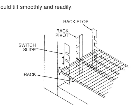
Rack Installation: Insert the rack by placing the left pivot point just behind the switch slide. Line up the rack evenly and push it straight back until the pivot points engage with the rack pivots. The rack should tilt smoothly.
Electrical Connections
Warning: All electrical and grounding connections must comply with the National Electrical Code (ANSI/NFPA-70) or local codes. Disconnect power and tag the switch before working on the circuit. Two 1-inch (25 mm) knockouts are provided at the left rear for conduit installation.
Operation
Push the main switch to ON. The pilot light will illuminate, and the cooling fan will start. Place the product on the front half of the rack to automatically activate the heaters at full power. If heaters do not activate, ensure the product is on the front half of the rack and that the rack is level and correctly inserted. Removing the product reverts the heaters to standby mode (25% power). On model 1048, use the top and bottom switches to control the left and right sides respectively. Rack height can be adjusted to control heat intensity: lower levels for warming, upper levels for finishing/glazing.
Cleaning
Warning: Disconnect electrical power before cleaning. Allow the unit to cool completely. Clean with soap and water, rinse, and dry with a soft cloth. The rack can be removed and cleaned like a standard utensil. The heating elements are self-cleaning; do not immerse them in water.
Practical help
Common problems
Heaters do not light
Check if the unit is in standby mode (no product on rack). If the pilot light is off and fan is not running, check for a blown fuse or tripped circuit breaker. If one heater is lit but the other is not, it may be a burnout or loose connection.
Cooling fan does not run
If the pilot light is off and heaters do not function, check for a blown fuse or tripped circuit breaker. If the pilot light is on, it may be a loose connection.
Heaters do not come on full power when product is placed
Ensure the product is placed on the front half of the rack to trip the actuating switch. Verify the rack is level and correctly inserted.
Before use
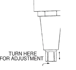
- Ensure the unit is level side to side and front to back.
- Verify the electrical supply matches the unit requirements (208 or 240V, Single Phase).
- Ensure legs are installed for countertop models.
- Check that heating elements are properly seated in their sockets.
- Ensure the rack is correctly inserted and tilts smoothly.
Specs in practice
- Heating Elements
- Varies by model: 1200W, 1800W, or 1050W elements.
Images and diagrams
- Heater Installation: Push one end into socket, swing other end up, release to snap into place.
- Rack Installation: Insert left pivot behind switch slide, push back until pivots engage.
Model compatibility
- Pass-through models must not be wall-mounted.
- Avoid installation directly over charbroilers or fryers to prevent grease damage to elements.

Manual page author
Emily Carter
User documentation editor
Prepares concise manual descriptions and highlights the most useful setup, operation, and maintenance information for readers.