Tools / Soldering Stations
Weller WT 2M Control Unit User Manual
Quick guide for the Weller WT 2M soldering control unit. Includes setup instructions, menu navigation, parameter settings, and tool compatibility.
Quick answers from the manual
Quick answer
- The Weller WT 2M is a soldering control unit. To set it up, ensure 50mm of clearance, connect the power and tool, and use the side switch to power on. Temperature and settings are adjusted via the front panel menu. p. 3, 4, 5
Key actions
- Powering on the unit p. 5
- Adjusting temperature p. 6
- Accessing the menu p. 8
First start
- Connect power and tool, ensure 50mm clearance, and switch on. p. 3, 4, 5
Show 3 more answers Show less
Problems and fixes
Tool combination not possible
Check compatibility matrix on page 13.
p. 13Technical specifications
| Parameter | Value | Meaning | Pages |
|---|---|---|---|
| Standby Temperature | 100 - 300 °C / 200 - 600 °F | Adjustable range for standby mode. | p. 8, 10 |
| Standby Time | 1 - 99 min | Time before entering standby. | p. 8, 10 |
| OFF Time | 1 - 999 min | Automatic shutdown time. | p. 8, 10 |
| Process Window | 1 - 99 °C / 1 - 180 °F | Temperature deviation range. | p. 9, 10 |
Where to find it in the PDF
- Setup and Connections p. 3, 4
- Operation p. 5, 6, 7
- Menu Settings p. 8, 9, 10, 11
- Compatibility p. 13, 14
Table of contents
Manual images
Click an image to enlargeQuick guide from the manual
The Weller WT 2M is a professional soldering control unit. This guide covers the essential setup, operation, and configuration steps required to use the device effectively.
Setup and Installation
Proper installation is critical for the safe and efficient operation of the control unit:
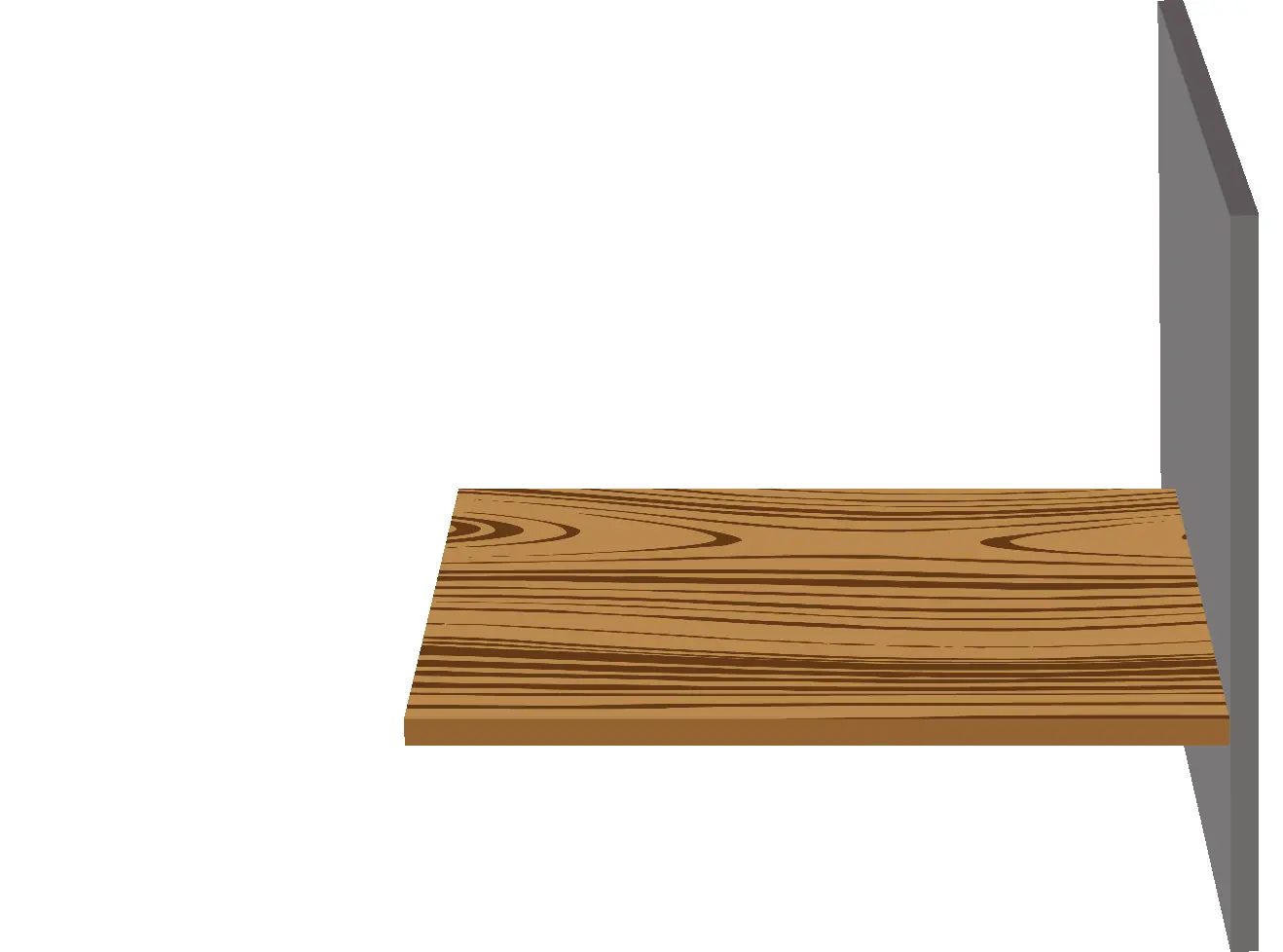
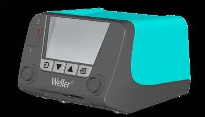

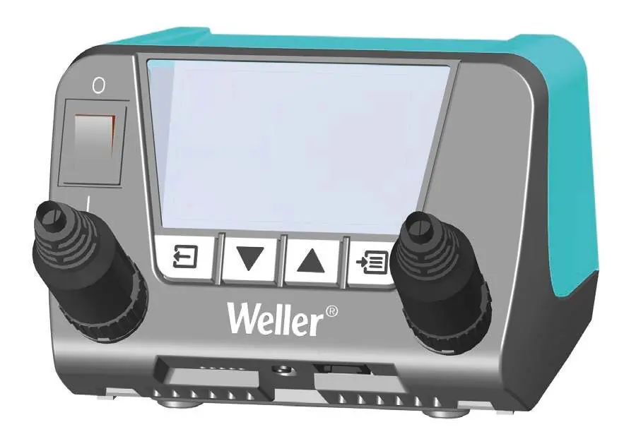
- Clearance: Ensure there is at least 50 mm of free space around the unit to allow for proper ventilation.
- Connections: Connect the power cable to the appropriate voltage source (110-127 V or 220-230 V). Connect the soldering tool to the designated port on the front of the unit.
- Powering On: Use the power switch located on the side of the unit to turn it on.
Operation and Temperature Adjustment
The unit features a digital display showing the current temperature of the connected tools.
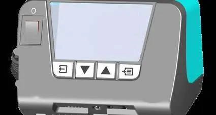
- Adjusting Temperature: Use the arrow buttons (up/down) to set the desired temperature for the connected soldering tool.
- Menu Navigation: Press and hold the Menu button for 3 seconds to access the configuration settings.
Menu Parameters
The menu allows you to customize various operational parameters:
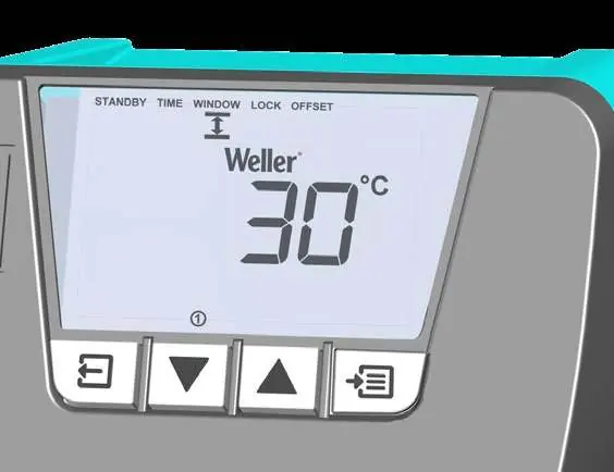
- Standby Temperature: Adjustable between 100 - 300 °C (200 - 600 °F).
- Standby Time: Adjustable between 1 - 99 minutes.
- OFF Time: Adjustable between 1 - 999 minutes (automatic shutdown).
- Process Window: Adjustable between 1 - 99 °C (1 - 180 °F).
- Lock: Security lock function (1 - 999).
- Offset: Temperature compensation between -40 - +40 °C (-72 - +72 °F).
- Sensitivity: Adjustable between 1 - 5.
- LCD Brightness: Adjustable between 0 - 100%.
Tool Compatibility
The WT 2M is compatible with a wide range of Weller soldering tools. Always refer to the compatibility matrix provided in the manual to ensure your specific tool set is supported by the control unit. Some combinations may result in power reduction to 150 W, while others may not be possible.
Manufacturer information
Weller Tools
Practical help
Common problems
Tool not recognized or not functioning
Check the compatibility matrix on page 13 to ensure the tool is supported by the WT 2M control unit.
Unit overheating or shutting down
Ensure there is at least 50 mm of clearance around the unit for proper ventilation.
Before use
- Ensure the unit is placed on a stable surface.
- Maintain at least 50 mm of clearance for ventilation.
- Connect the power cable to a compatible voltage outlet.
- Connect the soldering tool securely to the front port.
- Verify the tool is compatible using the compatibility matrix.
Show more Show less
Specs in practice
- Standby Temperature
- The temperature the tool drops to when not in active use to save energy and tip life.
- Process Window
- Defines the allowable temperature deviation range.
Images and diagrams
- Page 3: Shows the required 50mm clearance for the unit.
- Page 4: Illustrates power and tool connections.
- Page 8: Displays the menu navigation flow.
Model compatibility
- Refer to the compatibility table on page 13 for specific tool support.
- Some tool combinations may limit power output to 150 W.

Manual page author
Emily Carter
User documentation editor