Electronics / Networking
User Manual for Westermo Viper 20A-PoE Series
Comprehensive user guide for the Westermo Viper 20A-PoE series managed switches. Includes installation instructions, safety guidelines, hardware overview, connector pinouts, and technical specifications for railway-grade networking...
Quick answers from the manual
Quick answer
- The Viper 20A-PoE series are managed 20-port routing switches designed for railway rolling stock. They feature PoE, IP67 protection, and high vibration resistance, requiring installation by qualified personnel. p. 10
Key actions
- Connect protective earth first during installation. p. 5, 17
- Use an external fuse for power supply protection. p. 5, 18
First start
- Ensure the device is mounted on a flat, stable surface and connected to a protective earth rail before applying power. p. 17, 18
Problems and fixes
ON LED is RED
Indicates an alarm condition or that the product is starting up.
p. 15
X1-X20 LED is YELLOW
Port alarm, or port is set in blocking state by link redundancy protocol.
p. 15Maintenance and reset
- Use a dry or slightly water-damp cloth to clean. Do not use harsh chemicals. p. 6
Technical specifications
| Parameter | Value | Meaning | Pages |
|---|---|---|---|
| Operating Temperature | -40 to +70°C | Operational temperature range. | p. 24 |
| Weight | 2.5 kg | Total weight of the unit. | p. 24 |
Where to find it in the PDF
- Hardware Overview p. 12
- Connector Pinouts p. 13, 14
- Installation p. 17, 18
Table of contents
Manual images
Click an image to enlargeQuick Guide from the Manual
The Viper 20A-PoE series consists of managed 20-port routing switches optimized for railway rolling stock. These devices are designed to withstand harsh environments, including vibration, extreme temperatures, and humidity. Installation must be performed by qualified service personnel. Ensure the protective earth conductor is connected first during installation and disconnected last during removal.
Safety and Regulations
Warning Levels: The manual uses specific warning levels to prevent injury or damage: WARNING (possible death/major injury), CAUTION (minor/moderate injury), NOTICE (misuse/confusion), and NOTE (important information).
- Safety During Installation: The product must be installed in an apparatus cabinet restricted to service personnel.
- Hazardous Voltage: Do not open an energized product.
- Protective Fuse: The power supply wiring must be sufficiently fused (IEC 60127 certified, T6A for HV models or T10A for LV models, 250 V).
- Fire Risk: Use telecommunication line cords with a cable diameter of AWG 26 or larger.
- ESD: Prevent electrostatic discharge damage by grounding your body.
- Hot Surface: The surface may become hot during operation.
Hardware Overview
The device features various M12 connectors for power, data, and console access. Key interfaces include:
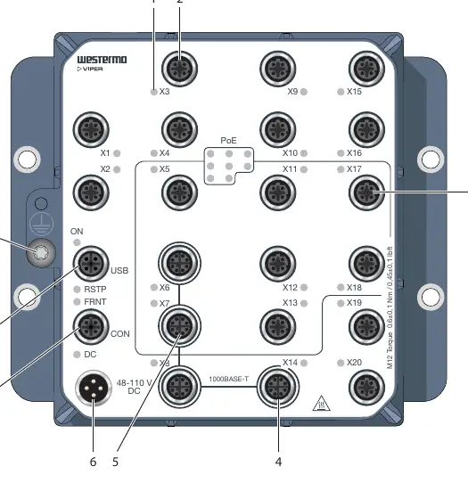
- 100 Mbps ports: Standard Ethernet connectivity.
- Gbps ports: High-bandwidth connectivity for devices like NVRs.
- PoE ports: Power over Ethernet for end devices.
- Console/USB ports: For management and configuration.
- LED Indicators: Provide status for power, link, traffic, and alarms.
Installation
Wall Mounting: The product can be mounted vertically or horizontally using four 7 mm bores. Use M5, M6, or 1/4" screws with 12 mm washers on a flat, stable surface.
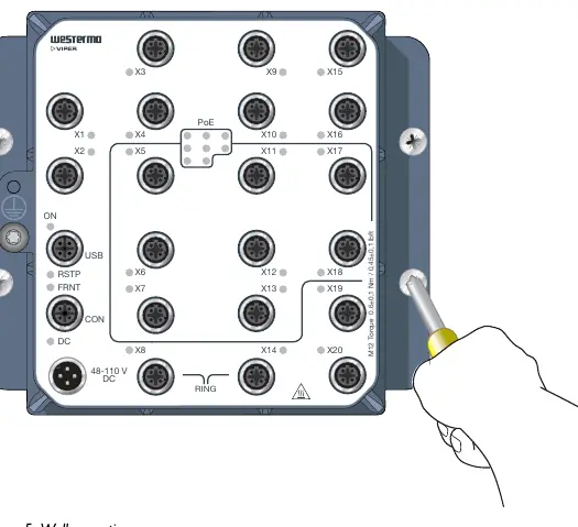
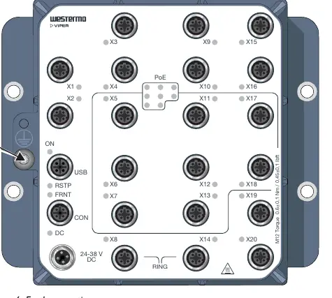
Protective Earth: For correct function, the earth connection must be properly connected to a designated PE rail.
Connection of Cables: Recommended tightening torque for M12 connectors is 0.6 Nm. Ensure pins are connected correctly before tightening.
Cooling: The product relies on convection cooling. Ensure ambient temperature is within specifications and airflow is not obstructed.
Specifications
The Viper 20A-PoE series supports:
- Power: LV units (24-38 VDC) and HV units (48-110 VDC).
- Environmental: IP67 protection, operating temperature -40 to +70°C.
- Standards: EN 50155, IEEE 1478, EN 45545-2 (fire protection).
Practical help
Common problems
Product surface becomes hot
This is normal during high-temperature operation; be aware of touch temperature limits.
ESD damage
Prevent damage to internal parts by discharging your body to a grounding point (e.g., use a wrist strap) before handling.
Power failure (DC LED red)
Check if input voltage is < 70% of minimum nominal voltage.
Unused connectors
Must be covered by a protective cap (delivered with the product) and tightened to the specified torque.
Before use
- Verify that the application does not exceed safe operating specifications.
- Ensure qualified service personnel perform the installation.
- Confirm the power supply is fused according to IEC 60127 (T6A/T10A).
- Prepare M5, M6, or 1/4" screws with 12 mm washers for mounting.
- Ensure a protective earthing conductor is available for connection.
Images and diagrams
- Hardware Overview: Identifies location of all ports (100 Mbps, Gbps, PoE, Console, USB) and LED indicators.
- Connector Pinout: Details signal assignments for Power (HV/LV), Console, USB, and Ethernet ports.
- Wall Mounting: Shows the 4-point mounting pattern and screw requirements.
- Earth Connection: Illustrates the grounding point screw location.
Model compatibility
- PoE ports are not isolated from each other.
- Requires shielded CAT5e cable or better for Ethernet connections.
- Compatible with WeOS 4 operating system.

Manual page author
David Miller
Documentation analyst
Organizes user manual content into clear summaries, with attention to model details, product context, and everyday usability.