Electronics / Networking
Westermo Viper 12A-PoE Series Ethernet Switch User Guide
Quick guide for the Westermo Viper 12A-PoE series managed Ethernet switches. Includes installation, wiring, safety, LED indicators, and technical specifications.
Table of contents
Manual images
Click an image to enlargeQuick guide from the manual
The Westermo Viper 12A-PoE series consists of managed 12-port routing switches designed for the railway rolling stock market. These devices are built to withstand harsh environments, including extreme temperatures, vibration, and humidity. Key installation requirements include mounting by qualified personnel, connecting a protective earth conductor, and using appropriate M12 connectors with specified torque.
Product Description
The Viper 12A-PoE series features managed switches with eight PoE ports. They are designed for high-bandwidth devices and offer IP67 protection against water and dust. The switches utilize the WeOS operating system for resilient networking, including the FRNT ring protocol.
Installation
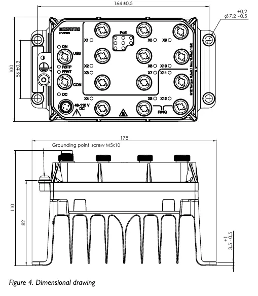
Wall Mounting: The product can be mounted vertically or horizontally using four 7 mm bores. Use four M5, M6, or 1/4" screws with 12 mm washers on a flat, stable surface.

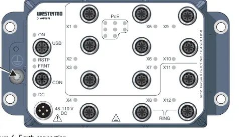
Protective Earth Connection: For correct function, the earth connection must be properly connected to a designated PE rail. Use a Torx T25 driver with a torque of 3.2 Nm.
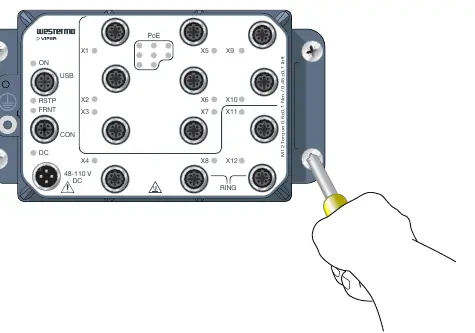
Connection of Cables: All M12 connections are screw connections. The recommended tightening torque for M12 connectors is 0.6 Nm. Ensure pins are connected correctly before tightening. Unused connectors must be covered with protective caps to maintain the IP67 rating.
LED Indicators
- ON: Indicates power status. Green means OK; Red indicates an alarm or startup; Blinking indicates location mode or pending factory reset.
- RSTP: Indicates RSTP status (Off/Enabled/Root switch).
- FRNT: Indicates FRNT status (Off/OK/Error/Focal point).
- DC: Indicates power input status (Green > 70% nominal, Red < 70%).
- X1 to X12: Indicates link status (Off/Link established/Traffic/Port alarm).
- PoE: Indicates PoE power consumption status.
Safety and Maintenance
The product must be installed in an apparatus cabinet restricted to service personnel. Do not open an energized product. The power supply wiring must be sufficiently fused (IEC 60127 certified, T6A for HV models, T8A/T10A for LV models). Clean the product with a dry or slightly damp cloth; do not use harsh chemicals or paint the unit.
Technical Specifications
The series is divided into HV (48-110 VDC) and LV (24-38 VDC) models. PoE ports provide up to 30W on one port (PoE+) with a maximum of 80W total. The operating temperature range is -40 to +70°C.
Practical help
Common problems
Product has no power
Check power connection and ensure input voltage is within the specified range (HV: 48-110 VDC, LV: 24-38 VDC).
Port alarm (Yellow LED)
Indicates a port alarm or the port is set in a blocking state by the link redundancy protocol.
FRNT error (Red LED)
Check the FRNT configuration.
Before use
- Ensure installation is performed by qualified service personnel.
- Verify power source matches HV (48-110V) or LV (24-38V) requirements.
- Connect protective earth conductor to the designated terminal.
- Use M12 connectors with recommended torque (0.6 Nm).
- Ensure unused connectors are covered with protective caps.
Images and diagrams
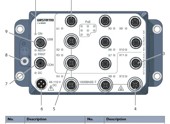
- Figure 3: Shows location of interface ports (M12) and LED indicators.
- Figure 4: Dimensional drawing for wall mounting.
- Figure 5: Wall mounting procedure.
- Figure 6: Protective earth connection point.
Model compatibility
- Requires M12 connectors.
- HV models: 48-110 VDC.
- LV models: 24-38 VDC.

Manual page author
David Miller
Documentation analyst
Organizes user manual content into clear summaries, with attention to model details, product context, and everyday usability.