Electronics / Networking
User Manual for Westermo Viper 12A Series Ethernet Switch
Quick guide for the Westermo Viper 12A Series Ethernet switch. Includes installation instructions, wiring diagrams, LED status indicators, and technical specifications.
Table of contents
Manual images
Click an image to enlargeQuick guide from the manual
The Westermo Viper 12A series consists of managed 12-port Ethernet switches designed for railway rolling stock. This guide covers essential installation, safety, and operational procedures. Always ensure the device is installed by qualified personnel and connected to a protective earth terminal.
Product Description
The Viper 12A series is optimized for demanding environments, featuring IP67 protection against water and dust, and a GORE-TEX membrane to prevent internal condensation. It supports redundant power inputs and provides high-level isolation between interfaces.
Hardware Overview
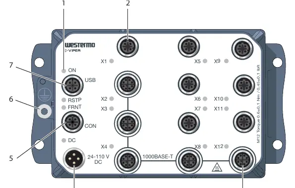
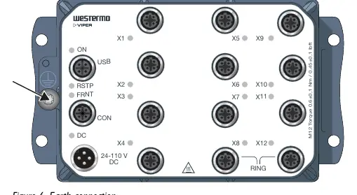
The device features various M12 connectors for Ethernet, power, console, and USB. LED indicators provide real-time status updates for power, link activity, and redundancy protocols (RSTP/FRNT).
Installation
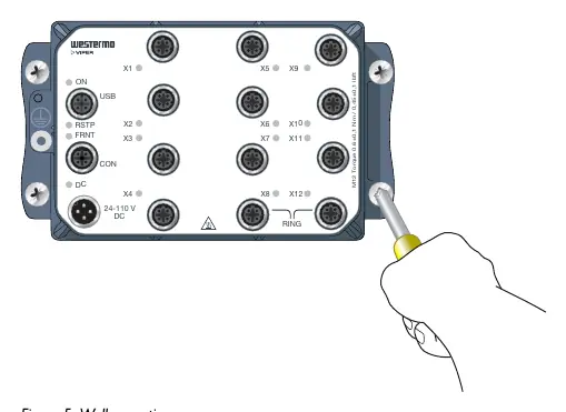
Wall Mounting: The switch can be mounted vertically or horizontally using four M5, M6, or 1/4 inch screws with 12 mm washers on a flat, stable surface.
Protective Earth: For correct function, the earth connection must be properly connected to a designated PE rail.
Connection of Cables: All M12 connections are screw-type. The recommended tightening torque is 0.6 Nm. Ensure pins are connected correctly before tightening. Unused connectors must be covered with protective caps to maintain the IP67 rating.
Safety and Maintenance
- Protective Fuse: The power supply must be fused externally with an IEC 60127 certified T1.6 A, 250 V fuse.
- Care: Do not drop or shake the product. Clean with a dry or slightly damp cloth; do not use harsh chemicals or paint.
- Hot Surface: The surface may become hot during operation at high temperatures.
- ESD: Prevent electrostatic discharge by grounding your body before handling internal parts.
Specifications
The device operates on 24 to 110 VDC. It supports 10/100 Mbps and 1000 Mbps (Gbps) Ethernet speeds depending on the model. The operating temperature range is -40 to +70°C.
Practical help
Common problems
Device not powering on
Check the external power supply and ensure the external T1.6 A, 250 V fuse is intact.
Port alarm or blocking state
Check the LED status; a yellow light indicates a port alarm or that the port is blocked by a link redundancy protocol.
Configuration loss
It is recommended to keep a Westermo USB plug connected to the USB port for easy configuration backup and restoration.
Before use
- Ensure the installation environment is within the specified temperature range (-40 to +70°C).
- Verify the power supply is fused with an external T1.6 A, 250 V fuse.
- Ensure a protective earth conductor is connected to the metallic housing.
- Check that all unused M12 connectors are covered with protective caps.
- Verify that the mounting surface is flat and stable.
Specs in practice
- Rated voltage
- 24 to 110 VDC input range.
Images and diagrams
- Hardware Overview: Identifies the location of LED indicators, power connection, console port, and Ethernet ports.
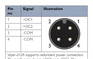
- Connector Pinouts: Details signal assignments for Power, Console, USB, and Ethernet ports.
- Wall Mounting: Illustrates the use of four M5, M6, or 1/4 inch screws for installation.
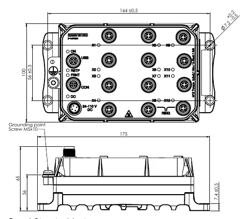
- Earth Connection: Shows the designated grounding point on the chassis.
Model compatibility
- Requires shielded CAT5e cable or better for Ethernet connections.
- Supports redundant power input.
- Compatible with WeOS 4 operating system.

Manual page author
David Miller
Documentation analyst
Organizes user manual content into clear summaries, with attention to model details, product context, and everyday usability.