Electronics / Networking
User Guide for Westermo Viper 20A Series Ethernet Switch
Comprehensive user guide for the Westermo Viper 20A Series 20-port Ethernet switches. Includes installation, safety, wiring, and technical specifications for railway and industrial applications.
Quick answers from the manual
Quick answer
- The Viper 20A Series are managed 20-port Ethernet switches designed for railway and industrial environments, featuring M12 connectors, IP67 protection, and redundant power inputs. p. 9
Key actions
- Wall mounting p. 15
- Protective earth connection p. 15
Problems and fixes
Device not powering on
Check power supply (24-110 VDC), verify redundant power connections, and ensure the external fuse (T1.6 A, 250 V) is intact.
p. 5, 16Maintenance and reset
- Clean with a dry or slightly water-damp cloth. Do not use harsh chemicals or paint the product. p. 6
Technical specifications
| Parameter | Value | Meaning | Pages |
|---|---|---|---|
| Operating Temperature | -40 to +70°C | Operational range | p. 22 |
| Weight | 1.7 kg | Device weight | p. 22 |
Where to find it in the PDF
- Hardware Overview p. 10
- Installation p. 15
- Specifications p. 18
Table of contents
Manual images
Click an image to enlargeQuick guide from the manual
The Westermo Viper 20A Series are managed 20-port Ethernet switches designed for demanding environments, such as railway rolling stock. Key requirements for operation include installation by qualified service personnel, connection to a protective earth rail, and the use of an external IEC 60127 certified fuse (T1.6 A, 250 V). The device relies on convection cooling and must be installed in a location with adequate airflow.
Product Description
The Viper 20A series consists of managed routing switches optimized for high-bandwidth applications. Features include:
- IP67 protection against water and dust.
- GORE-TEX membrane to prevent internal condensation.
- Redundant power input (24-110 VDC).
- High MTBF for reliability in extreme temperatures and vibration.
- WeOS 4 operating system with Layer 3 routing capabilities.
Installation
Wall Mounting: The switch can be mounted vertically or horizontally on a flat, stable surface using four M5, M6, or 1/4" screws with 12 mm washers.

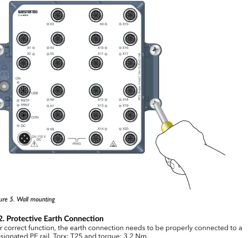
Protective Earth: For correct function, the earth connection must be properly connected to a designated PE rail using a Torx T25 tool with a torque of 3.2 Nm.
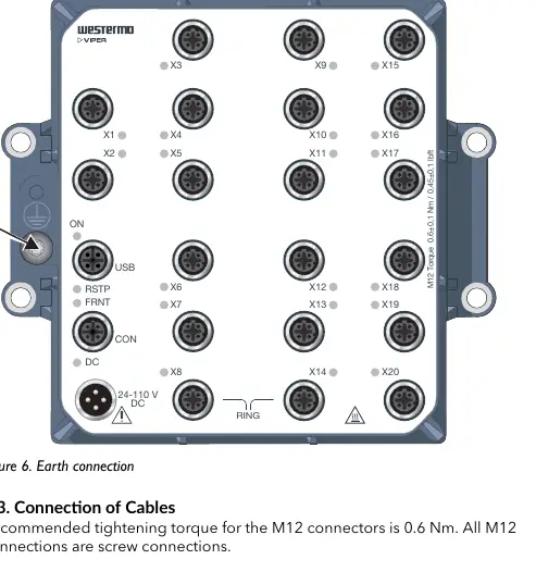
Cabling: All M12 connections are screw-type. Recommended tightening torque for M12 connectors is 0.6 Nm. Ensure pins are connected correctly before tightening. Unused connectors must be covered with the provided protective caps to maintain IP67 ingress protection.
LED Indicators
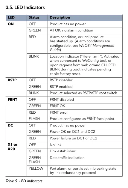
The device features several LED indicators to monitor status:
- ON: Indicates power status and alarm conditions.
- RSTP: Shows status of the Rapid Spanning Tree Protocol.
- FRNT: Indicates status of the FRNT ring protocol.
- DC: Monitors power input status (DC1 and DC2).
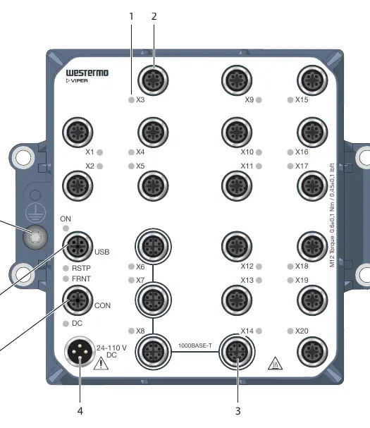
- X1 to X20: Indicates link status and data traffic for individual ports.
Specifications
The Viper 20A series operates on a nominal voltage of 24-110 VDC (operating range 16.8 to 143 VDC). It is designed for an operational temperature range of -40 to +70°C. The device weighs 1.7 kg and is rated for IP67 ingress protection.
Practical help
Common problems
Device not powering on
Check power supply (24-110 VDC), verify redundant power connections, and ensure the external fuse (T1.6 A, 250 V) is intact.
Link not established
Check cable connections, ensure M12 connectors are tightened to 0.6 Nm, and verify the use of shielded CAT5e cables or better.
Overheating or hot surface
Ensure proper convection cooling and that the ambient temperature is within the specified -40 to +70°C range.
Before use
- Ensure installation is performed by qualified service personnel.
- Verify power supply is within 24-110 VDC range.
- Install an external IEC 60127 certified fuse (T1.6 A, 250 V).
- Connect the protective earth terminal to a designated PE rail.
- Use shielded CAT5e cables or better for all Ethernet connections.
- Cover all unused connectors with protective caps.
Specs in practice
- Operating Voltage
- 16.8 to 143 VDC (nominal 24-110 VDC).
Images and diagrams
- Figure 3 shows the location of all interface ports and LED indicators.
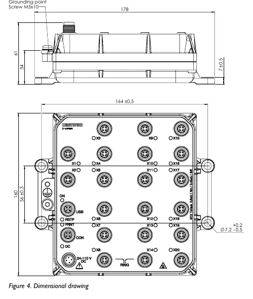
- Figure 4 provides the dimensional drawing in mm.
- Figure 5 illustrates the wall mounting procedure.
- Figure 6 illustrates the protective earth connection point.
Model compatibility
- Compatible with WeOS 4 operating system.
- Requires shielded CAT5e cable or better for 100 Mbps and Gbps ports.
- Designed for railway rolling stock and industrial environments.

Manual page author
Michael Turner
Technical manual editor
Reviews PDF manuals for structure, safety notes, and practical product details so readers can find the right information quickly.