HVAC / Air Conditioners
User Manual for ACiQ PTAC-B Series Packaged Terminal Air Conditioner
Quick guide for ACiQ PTAC-B series air conditioners. Includes installation instructions, DIP switch configurations, control panel operation, maintenance, and troubleshooting.
Table of contents
Manual images
Click an image to enlargeQuick Guide
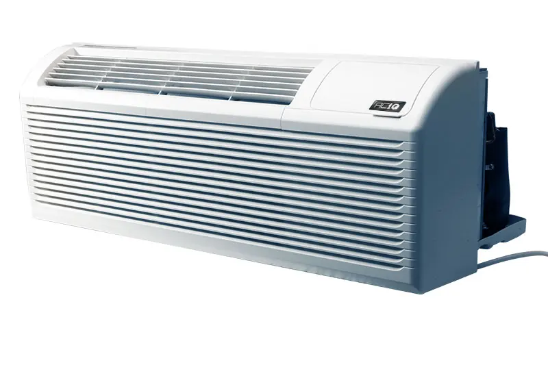
The ACiQ PTAC-B series is a packaged terminal air conditioner and heat pump. This manual provides essential information for installation, operation, and maintenance. Always ensure the unit is properly grounded and installed according to local electrical codes. For 265V models, a subbase kit is required for permanent wiring.
Installation
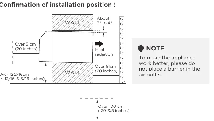
Installation should be performed by authorized personnel. Ensure the wall sleeve is installed level to allow for proper condensation drainage. The unit must be secured with four screws and washers through the flange holes. For 265V models, install the subbase kit and connect power wiring on-site, ensuring the product plug is inserted into the subbase power jack.
Operation
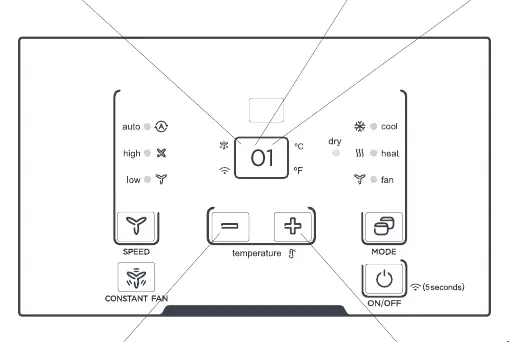
The unit can be controlled via the onboard control panel or an optional wall-mounted thermostat. To use a wall thermostat, the unit must be configured via DIP switches. The control panel allows for mode selection (Cool, Dry, Heat, Fan), temperature adjustment, and fan speed control. Note that the compressor has a 3-minute minimum run time and restart delay to prevent short cycling.
DIP Switch Configuration
DIP switches are used to customize unit features. Ensure the unit is powered OFF before changing settings. Key configurations include:
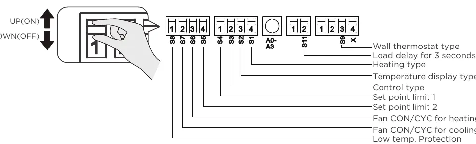
- S1: Electric Heat Only vs. Electric Heat and Pump Heat.
- S3: Wall Thermostat Enable vs. Control Panel Enable.
- S4*S5: Setpoint temperature range limits.
- S6/S7: Fan continuous run vs. cycle mode.
- S8: Low temperature protection.
- Sw11: Load delay for 3 seconds.
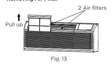
Maintenance
Regular maintenance is crucial for efficiency. Clean the air filters every two weeks by pulling them up and out of the unit. Vacuum off heavy soil and rinse with water. Ensure the outdoor coil is checked regularly for dirt build-up; if clogged, it should be professionally cleaned. Never use high-pressure spray on the coils.
Troubleshooting
If the unit does not start, check the power plug, circuit breaker, and ensure the unit is not in a protection mode. If the unit is not cooling or heating, check for blocked airflow, dirty filters, or incorrect setpoint limits. If water is dripping inside, verify that the wall sleeve is installed level.
Manufacturer information
ACiQ
Practical help
Common problems
Unit does not start
Check if the unit is plugged in, the circuit breaker is tripped, or if the unit is in a protection mode.
Unit not cooling or heating
Check for blocked air discharge, dirty filters, or if the setpoint limits are preventing the desired temperature.
Water dripping inside
Ensure the wall sleeve is installed level for proper condensation drainage.
Ice or frost on indoor coil
Check for dirty filters or low outdoor temperatures (below 55°F/13°C). Switch to FAN mode until ice melts.
Before use
- Ensure the unit is properly grounded.
- Verify the power supply matches the unit requirements.
- Check that the wall sleeve is installed level.
- Ensure air filters are clean and properly inserted.
- Confirm that air inlets and outlets are not blocked by curtains or furniture.
Specs in practice
- DIP Switches
- Internal switches used to configure heating type, setpoint limits, and fan operation modes.
- Front Desk Control
- Allows the unit to be turned on/off via an external 24VAC signal.
Images and diagrams
- DIP Switch Settings: Refer to Table 1 on page 21/23 for configuration options.
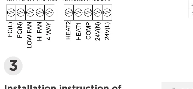
- Wiring: Terminal designations for wall thermostats are detailed on page 26.
- Filter Removal: Pull up on the air filters as shown in Fig 13 on page 32.
Model compatibility
- 265V models require a specific subbase kit (MWP-S3500/20A).
- Wall thermostats must be compatible with the unit type (heat pump vs. no heat pump).

Manual page author
David Miller
Documentation analyst
Organizes user manual content into clear summaries, with attention to model details, product context, and everyday usability.