Lighting / Fixtures
Acroma 2081612AZ Chandelier Installation Manual
Installation guide for the Acroma 2081612AZ chandelier. Includes safety warnings, hardware list, step-by-step assembly instructions, and wiring diagrams.
Quick answers from the manual
Quick answer
- This manual provides installation instructions for the Acroma 2081612AZ chandelier, including hardware lists, assembly steps, and wiring diagrams. p. 1, 2, 3, 4
Key actions
- Turn off power p. 1
- Connect wires p. 4
First start
- Ensure power is off, assemble the fixture components, mount to the junction box, and connect wires according to the diagram. p. 2, 3, 4
Show 2 more answers Show less
Technical specifications
| Parameter | Value | Meaning | Pages |
|---|---|---|---|
| Bulb Type | 12 x Max 40W Candelabra Base | Maximum wattage per bulb | p. 1 |
Where to find it in the PDF
- Safety and Pre-Installation p. 1
- Hardware and Assembly p. 2
- Assembly Steps p. 3
- Wiring Diagram p. 4
Table of contents
Manual images
Click an image to enlargeQuick guide from the manual
Before beginning the installation of your Acroma 2081612AZ chandelier, ensure you have all the necessary tools and that the power is disconnected at the circuit breaker. Always use a voltage tester to confirm the power is off before touching any wires. Protect the fixture components by placing them on a soft, non-abrasive surface like carpet or cardboard during assembly.
Hardware included
The package includes the following components:
- Mounting plate
- Support screws (long) x 2
- Outlet box screws (short) x 2
- Hex nuts x 2
- Green ground screw
- Wire connectors x 3
- Canopy
- Chain end loops x 8
- Flat washers x 2
- Finials x 2
- Chain
- Socket sleeves x 12
- Connector ring
- Arms x 12
Assembly instructions
Assembly is accomplished by determining the required length of the stem or chain, attaching the mounting plate to the junction box, making electrical connections, and hanging the fixture.
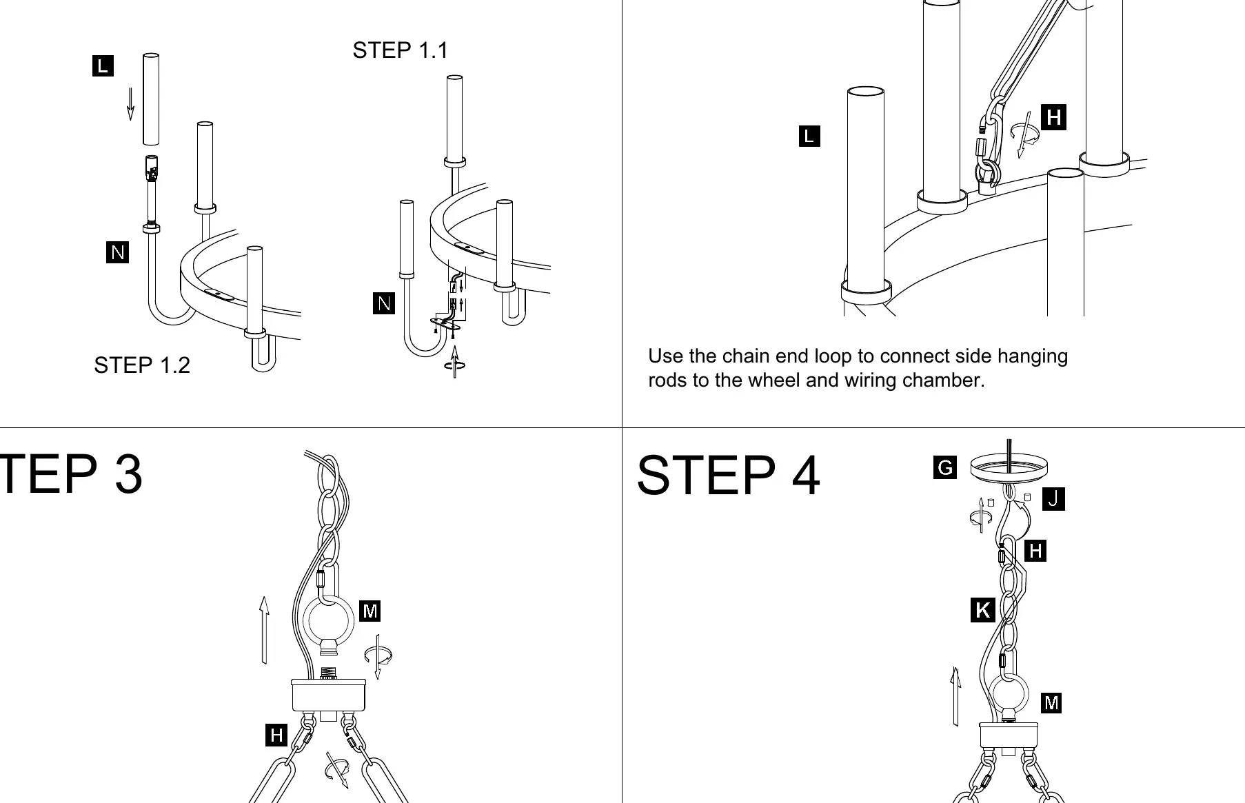
- Step 1: Attach the socket sleeves (L) to the arms (N).
- Step 2: Use the chain end loops to connect the side hanging rods to the wheel and wiring chamber.
- Step 3: Assemble the main chain and connector ring (M) to the top of the fixture.
- Step 4: Attach the canopy (G) and chain (K) assembly.
- Step 5: Connect the lanyard to the mounting bracket to support the fixture while making wire connections.
Wiring instructions
Follow these wiring steps carefully:
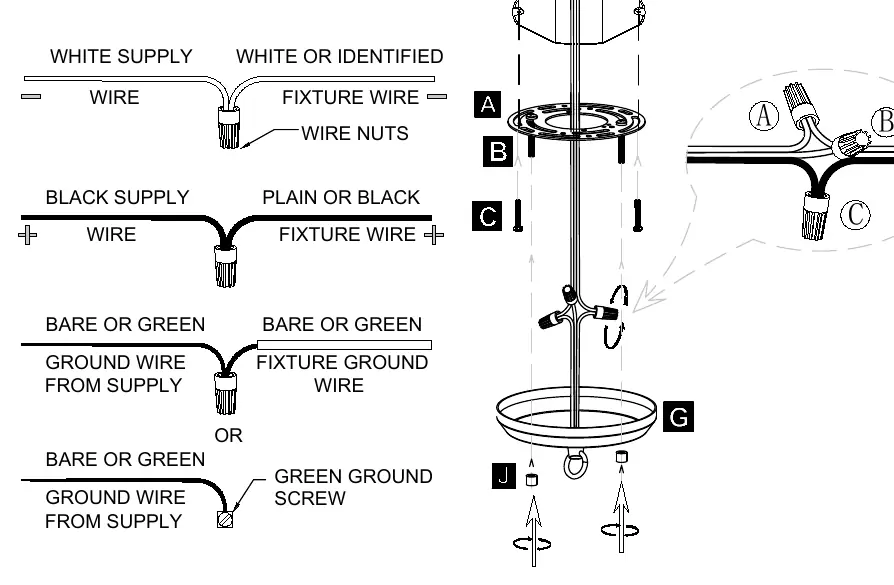
- Connect the White Supply Wire to the White or Identified Fixture Wire using wire nuts.
- Connect the Black Supply Wire to the Plain or Black Fixture Wire using wire nuts.
- Connect the Bare or Green Ground Wire from Supply to the Fixture Ground Wire or the Green Ground Screw on the mounting plate.
Safety information
For your protection, read and understand all instructions before attempting to assemble, install, or operate this product. Failure to do so could lead to electrical shock, fire, or other injuries. If you have any electrical questions, consult a qualified electrician. Use tools with insulated handles and ladders made of wood or fiberglass.
Practical help
Common problems
Fixture does not light up
Verify that the circuit breaker is on and that all wire connections are secure and correctly matched.
Unsure about electrical wiring
Consult a qualified electrician or local authorities for code requirements.
Before use
- Turn off power at the circuit breaker or fuse box
- Use a voltage tester to ensure wires are not live
- Gather required tools: Phillips screwdriver, wire stripper, pliers, safety goggles, electrical tape
- Place fixture on a soft, non-abrasive surface to prevent damage
- Verify all hardware parts are present
Show more Show less
Specs in practice
- 12 x Max 40W Candelabra Base
- The fixture is designed for 12 bulbs, each with a maximum wattage of 40W, using a candelabra base.
Images and diagrams
- Step 1: Shows attachment of socket sleeves to arms.
- Step 2: Shows connection of side hanging rods to the wheel.
- Step 5: Wiring diagram illustrating connections for supply wires to fixture wires.
Model compatibility
- Requires a junction box for mounting.
- Consult a qualified electrician if new wiring is required.

Manual page author
David Miller
Documentation analyst