Industrial / I/O Modules
Installation Instructions for Allen-Bradley 1734-OB2EP POINT I/O Protected Output Module
A comprehensive installation and setup guide for the Allen-Bradley 1734-OB2EP POINT I/O Protected Output Module. Includes wiring diagrams, mounting procedures, status indicator interpretation, and technical specifications.
Quick answers from the manual
Quick answer
- The 1734-OB2EP is a POINT I/O protected output module. Installation involves mounting the base on a DIN rail, setting the keyswitch, inserting the module, and wiring the RTB. It requires 24V DC power and is compatible with standard POINT I/O adapters. p. 1, 4, 5, 6
Key actions
- Install the mounting base on the DIN rail. p. 4
- Set the keyswitch on the mounting base. p. 4, 5
- Wire the module. p. 6
Problems and fixes
Module status LED flashing red
Recoverable fault.
p. 7
Network status LED red
Critical link failure.
p. 7Technical specifications
| Parameter | Value | Meaning | Pages |
|---|---|---|---|
| Number of outputs | 2 | 1 group of 2, non-isolated, sourcing | p. 8 |
| Output current rating | 2A per output | 4A per module | p. 8 |
Where to find it in the PDF
- Installation p. 4, 5
- Specifications p. 8
Table of contents
Manual images
Click an image to enlargeQuick guide from the manual
This document provides installation and configuration instructions for the Allen-Bradley 1734-OB2EP POINT I/O Protected Output Module. Key procedures include mounting the base on a DIN rail, installing the I/O module, wiring the removable terminal block (RTB), and interpreting status indicators.
About the Module
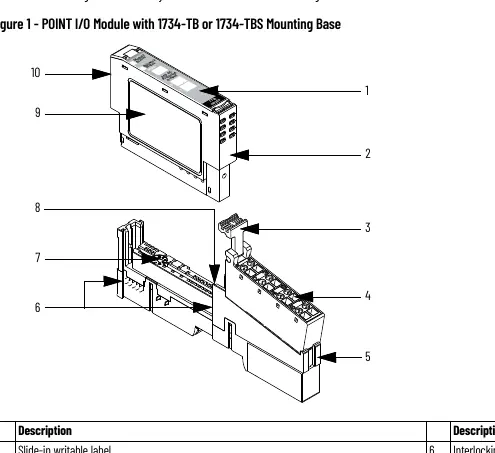
The POINT I/O wiring base assembly consists of a 1734-MB mounting base and an RTB (1734-RTB or 1734-RTBS). The module is designed for industrial environments (Pollution Degree 2, Overvoltage Category II). It is sensitive to electrostatic discharge; handle with care using a grounded wriststrap.
Installation
Mounting Base: Position the base vertically on the DIN rail. Slide it down to engage interlocking side pieces. Press firmly to snap into place. Ensure the orange DIN rail locking screw is in the horizontal position.
I/O Module: Use a bladed screwdriver to rotate the keyswitch on the mounting base to the number required for the module type. Verify the DIN rail locking screw is horizontal. Insert the module straight down into the base.
Removable Terminal Block (RTB): Insert the end opposite the handle into the base unit. Rotate the terminal block into the wiring base until it locks. If an I/O module is installed, snap the RTB handle into place.
Wiring
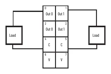
The module features two non-isolated, sourcing outputs. Field power is supplied from the internal power bus. Refer to the wiring diagram for specific terminal connections (0-7). Use a bladed screwdriver (3 mm diameter) to latch/unlatch wires in the RTB.
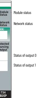
Status Indicators
The module has LEDs for Module Status, Network Status, and I/O Status. A solid green Module Status indicates normal operation. Flashing red/green indicates self-test mode. Refer to the indicator table for detailed troubleshooting of LED states.
Manufacturer information
Allen-Bradley
Practical help
Common problems
Module not communicating
Check Network Status LED. If red, it indicates a critical link failure or communication error.
Module cannot be inserted
Ensure the DIN rail locking screw is in the horizontal position and the locking mechanism is unlocked.
Open wire circuit detected
Check for missing load on the output (I/O status LED flashing red).
Before use
- Verify DIN rail is zinc-plated chromate-passivated steel.
- Ensure environment is Pollution Degree 2.
- Check that the keyswitch on the mounting base is set correctly.
- Confirm 24V DC power supply is available.
- Ensure proper grounding of the DIN rail.
Specs in practice
- On-state voltage
- Nominal 24V DC (10-28.8V DC range).
- Output current rating
- 2A per output, 4A per module.
- Isolation voltage
- 50V continuous (tested to 1250V AC).
Images and diagrams
- Figure 1 shows the module components including the slide-in label, RTB, and DIN rail locking screw.
- Wiring diagram illustrates connections for outputs 0 and 1, common (C), and supply (V).
Model compatibility
- Compatible with 1734-TB, 1734-TBS, 1734-TOP, or 1734-TOPS wiring base assemblies.
- Requires RSLogix 5000 software version 11 or later, or Studio 5000 Logix Designer version 20 or later.

Manual page author
Emily Carter
User documentation editor
Prepares concise manual descriptions and highlights the most useful setup, operation, and maintenance information for readers.