Industrial / I/O Modules
Installation Instructions for Allen-Bradley 1734-4IOL 4 Channel IO-Link Master Module
Comprehensive installation and configuration guide for the Allen-Bradley 1734-4IOL and 1734-4IOLK POINT I/O modules, covering mounting, wiring, status indicators, and technical specifications.
Quick answers from the manual
Quick answer
- The 1734-4IOL is a 4-channel IO-Link master module for POINT I/O systems. It supports IO-Link master communication or standard digital I/O (input/output) and requires specific EtherNet/IP adapters and software versions. p. 4
Key actions
- Install Mounting Base p. 6
- Install Module p. 6
- Wire Module p. 9
First start
- Ensure firmware compatibility (1734-AENT/R Series B v5.012+ or Series C v6.011+), install on DIN rail, wire according to mode, and configure via Studio 5000 Logix Designer v20+. p. 4
Problems and fixes
Module Status Flashing Red
A recoverable fault occurred.
p. 11
Network Status Red
Critical link failure; check communication.
p. 11Technical specifications
| Parameter | Value | Meaning | Pages |
|---|---|---|---|
| Field power bus supply | 24V DC (19.2V to 28.8V DC) | Operating voltage range | p. 12 |
| Communication rate | 4.8 kB, 38.4 kB, 230.4 kB | IO-Link communication speeds | p. 12 |
Where to find it in the PDF
- Installation p. 6, 7
- Specifications p. 12, 13
Table of contents
Manual images
Click an image to enlargeQuick guide from the manual
The Allen-Bradley 1734-4IOL is a 4-channel IO-Link master module designed for POINT I/O systems. It can be configured for IO-Link master communication or as a standard digital I/O module. This document provides essential instructions for installation, wiring, and configuration.
Installation
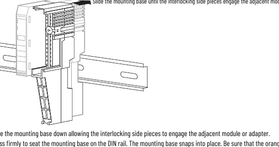
Mounting Base: Position the mounting base vertically above existing units. Slide it down to engage the interlocking side pieces with the adjacent module or adapter. Press firmly to seat it on the DIN rail. Ensure the orange DIN rail locking screw is in the horizontal position.
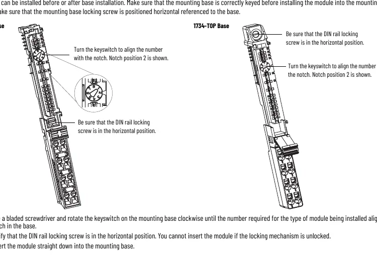

Module: Before installing the module, use a bladed screwdriver to rotate the keyswitch on the mounting base until the number required for the module type aligns with the notch. Verify the DIN rail locking screw is horizontal, then insert the module straight down into the base until it locks.
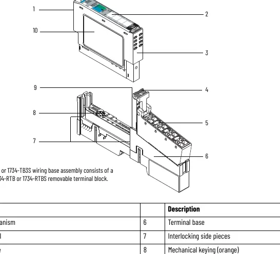
Removable Terminal Block (RTB): Insert the end opposite the handle into the base unit, rotate the terminal block into the wiring base until it locks, and snap the RTB handle into place.
Wiring
The module supports three wiring modes:
- IO-Link Mode: Connects IO-Link devices (actuators, sensors).
- Standard Digital Input Mode: Supports 2-wire or 3-wire inputs.
- Standard Digital Output Mode: Supports 2-wire outputs.
Power is supplied through the internal 24V DC power bus. Ensure power is removed before connecting or disconnecting the RTB to prevent electrical arcs, especially in hazardous locations.
Status Indicators
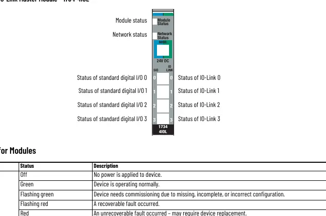
The module features LEDs for Module Status, Network Status, Channel Status, and IO-Link Status. A solid green Module Status indicates normal operation, while flashing red indicates a recoverable fault and solid red indicates an unrecoverable fault. Network status LEDs indicate connection state; flashing red/green indicates a communication faulted device.
Technical Specifications
- Field Power Bus Supply: 24V DC (19.2V to 28.8V DC).
- Communication Rate (IO-Link): 4.8 kB, 38.4 kB, 230.4 kB.
- Isolation Voltage: 50V (continuous), basic insulation.
- Input Filter: Independently settable in 1 ms intervals (0...65 ms).
- Operating Temperature: -20 to +55 °C (-4 to +131 °F).
Manufacturer information
Allen-Bradley
Practical help
Common problems
Module status flashing red
A recoverable fault occurred.
Module status solid red
An unrecoverable fault occurred; may require device replacement.
Network status flashing red
One or more I/O connections are in a timed-out state.
Network status solid red
Critical link failure; the device detected an error preventing network communication.
Before use
- Ensure power is removed before installation or wiring.
- Verify the mounting base is correctly keyed for the module.
- Ensure the DIN rail locking screw is in the horizontal position.
- Use a bladed screwdriver for terminal block wiring.
- Check that the environment meets Pollution Degree 2 requirements.
- Verify firmware compatibility with your adapter (1734-AENT/R Series B v5.012+ or Series C v6.011+).
Specs in practice
- Field power bus supply
- 24V DC (19.2V to 28.8V DC) required for operation.
- Communication rate
- Supports 4.8 kB, 38.4 kB, and 230.4 kB for IO-Link.
- Isolation voltage
- 50V (continuous), basic insulation type.
- Input filter
- Independently settable in 1 ms intervals (0...65 ms).
Images and diagrams
- Wiring diagrams illustrate 3-wire and 2-wire connections for IO-Link, Digital Input, and Digital Output modes.
- Status indicator diagrams show the location of Module, Network, and Channel status LEDs.
Model compatibility
- Requires 1734-AENT or 1734-AENTR Series B (firmware 5.012+) or Series C (firmware 6.011+).
- Requires Studio 5000 Logix Designer version 20 or later.

Manual page author
Michael Turner
Technical manual editor
Reviews PDF manuals for structure, safety notes, and practical product details so readers can find the right information quickly.