Industrial / Process Controllers
Installation Instructions for Allen-Bradley 1756-RM2 ControlLogix Redundancy Modules
Comprehensive installation guide for Allen-Bradley 1756-RM2, 1756-RM2K, and 1756-RM2XT ControlLogix Redundancy Modules. Includes hardware setup, fiber-optic connection procedures, safety precautions, and technical specifications.
Quick answers from the manual
Quick answer
- The 1756-RM2 modules provide redundancy for ControlLogix systems. Installation requires matching modules in the same slot of each chassis, connected via a 1756-RMCx fiber-optic cable. p. 6, 7
Key actions
- Install the redundancy module p. 6
- Connect fiber-optic cable p. 7
First start
- Install chassis, power supply, communication modules, and controller before installing the redundancy module. p. 6
Problems and fixes
System not synchronizing
Ensure components in the first and second chassis match exactly.
p. 6Technical specifications
| Parameter | Value | Meaning | Pages |
|---|---|---|---|
| Wavelength | 1310 nm | Operating wavelength | p. 8 |
| Max Cable Length | 10 km | Maximum fiber-optic cable length | p. 8 |
Where to find it in the PDF
- Module Overviews p. 5
- Hardware Installation p. 6
- Fiber-optic Connection p. 7
Table of contents
Manual images
Click an image to enlargeQuick Guide from the Manual
This document provides installation instructions for the ControlLogix Redundancy Modules (1756-RM2, 1756-RM2K, 1756-RM2XT). These modules are designed to work in pairs to supervise operating states and synchronize control data between chassis. Important: Ensure all power is off before installing or removing modules. Modules must be identical in firmware and hardware revisions and must occupy the same slot in their respective chassis.
Safety and Environment
- ESD Protection: The equipment is sensitive to electrostatic discharge. Use a grounded wrist strap and static-safe workstation.
- Hazardous Locations: Specific requirements apply for Class I, Division 2 and Zone 2 environments. Ensure the enclosure is IP54 rated or better.
- UV Radiation: This equipment is not resistant to sunlight or UV radiation.
- Port Protection: Keep port plugs installed in unused ports to maintain corrosive atmosphere ratings.
Hardware Installation

- Install the chassis and power supply.
- Install communication modules.
- Install the controller.
- Install the redundancy module: Align the circuit board with the top and bottom guides in the chassis and slide it in until flush.
Connecting Redundancy Modules
Use a 1756-RMCx fiber-optic communication cable (sold separately) to connect the modules.
- Remove the black protective channel cover on the first module.
- Remove protective caps from cable ends.
- Plug the cable connector into the CH1 or CH2 port on the first module.
- Plug the other end into the corresponding channel on the secondary module.
- Note: It is recommended to match channel to channel (CH1 to CH1, CH2 to CH2) for troubleshooting simplicity.
Technical Specifications
- Connector Type: LC-type (fiber-optic)
- Cable Type: 8.5/125 μm single-mode fiber-optic cable
- Max Length: 10 km
- Transmission Speed: 1000 Mbps
- Wavelength: 1310 nm
- Operating Temperature: 0 to 60 °C (1756-RM2/RM2K); -25 to +70 °C (1756-RM2XT)
Manufacturer information
Allen-Bradley
Practical help
Common problems
Redundancy system not synchronizing
Ensure modules are in the same slot in their respective chassis and that firmware/hardware revisions are identical.
Fiber link failure
Check for sharp bends in the cable and ensure it is not damaged. Verify the cable is not routed where it can be cut or abraded.
Corrosion issues in hazardous locations
Ensure port plugs are installed in all unused ports at all times.
Before use
- Verify all required components are present.
- Order 1756-RMCx fiber-optic cable if not available.
- Ensure firmware revisions match for both modules.
- Confirm chassis slot alignment.
- Ensure system power is off before installation.
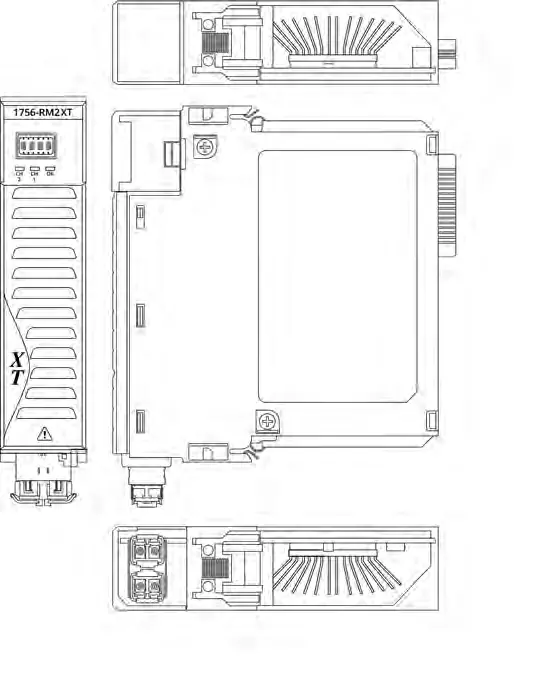
Images and diagrams
- Front view shows status indicators and CH1/CH2 ports.
- Side view illustrates the backplane connector alignment.
Model compatibility
- 1756-RM2 and 1756-RM2XT modules can only be used with other 1756-RM2 or 1756-RM2XT modules.
- XT modules must be used with an XT chassis.

Manual page author
Emily Carter
User documentation editor
Prepares concise manual descriptions and highlights the most useful setup, operation, and maintenance information for readers.