Industrial / I/O Modules
Installation Instructions for Allen-Bradley 1734-OW2, 1734-OW4, and 1734-OW4K POINT I/O Relay Output Modules
A comprehensive installation and wiring guide for Allen-Bradley POINT I/O 2 and 4 Relay Output Modules (1734-OW2, 1734-OW4, 1734-OW4K). This manual covers mounting, wiring diagrams, status indicator interpretation, hazardous location...
Quick answers from the manual
Quick answer
- This manual provides installation, wiring, and configuration instructions for Allen-Bradley POINT I/O 2 and 4 Relay Output Modules (1734-OW2, 1734-OW4, 1734-OW4K). p. 1
Key actions
- Install Mounting Base p. 6
- Install Module p. 6
- Install Removable Terminal Block p. 7
- Wire the Module p. 9
Problems and fixes
Module status indicator flashing red
Recoverable fault. Check configuration.
p. 12Technical specifications
| Parameter | Value | Meaning | Pages |
|---|---|---|---|
| Operating Temperature | -20 to +55 °C | Ambient operating range | p. 12, 13 |
| Backplane Power | 5V DC, 80-90 mA | Power consumption from backplane | p. 12 |
Where to find it in the PDF
- Installation p. 6, 7, 8
- Specifications p. 12, 13
Table of contents
Manual images
Click an image to enlargeQuick guide from the manual
This document provides essential installation, wiring, and operational instructions for the Allen-Bradley POINT I/O 2 and 4 Relay Output Modules (1734-OW2, 1734-OW4, 1734-OW4K). Users must be trained personnel and comply with all applicable codes and standards. The equipment is intended for use in Pollution Degree 2 industrial environments.
Installation
The module can be installed before or after the base installation. Ensure the mounting base is correctly keyed before installing the module.
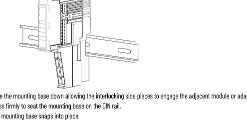

- Mounting Base: Position the base vertically above existing units, slide down to engage interlocking side pieces, and press firmly onto the DIN rail.
- Module: Use a bladed screwdriver to rotate the keyswitch on the mounting base until the number aligns with the notch. Ensure the DIN rail locking screw is in the horizontal position. Insert the module straight down into the base until it locks.
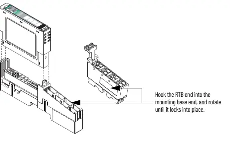
- Removable Terminal Block (RTB): Insert the end opposite the handle into the base unit, rotate until it locks, and snap the handle into place.
Wiring
Warning: Ensure power is removed or the area is nonhazardous before connecting or disconnecting wiring to avoid electrical arcs.
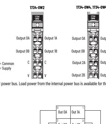
- 1734-OW2: Load power is available from the internal power bus. Connect V supply to pins 6 and 7, and V common to pins 4 and 5.
- 1734-OW4 / 1734-OW4K: Load power must be provided by an external power source. These modules cannot be powered from the internal power bus.
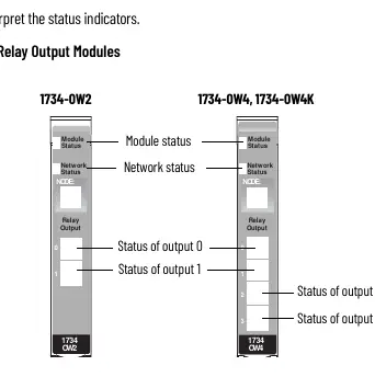
Status Indicators
The module features status indicators for Module Status and Network Status. A solid green Module Status indicates normal operation, while flashing red indicates a recoverable fault. Refer to the status indicator table in the manual for detailed troubleshooting of network and module states.
Safety and Environment
This equipment is sensitive to electrostatic discharge (ESD). Handle with care, use a grounding wriststrap, and store in static-safe packaging. For hazardous locations (Class I, Division 2), ensure the equipment is mounted in a suitable enclosure with proper wiring methods.
Manufacturer information
Allen-Bradley
Practical help
Common problems
Module will not insert into base
Ensure the keyswitch is set to the correct number and the DIN rail locking screw is in the horizontal position.
Electrical arc during installation
Ensure power is removed or the area is nonhazardous before inserting or removing modules or terminal blocks.
Module status indicator flashing red
Indicates a recoverable fault. Check system configuration and connections.
Before use
- Verify the environment meets Pollution Degree 2 requirements.
- Ensure DIN rail is zinc-plated chromate-passivated steel.
- Confirm power is removed before wiring.
- Check that the keyswitch is set correctly for the module type.
- Ensure the DIN rail locking screw is in the horizontal position.
Specs in practice
- Contact rating
- 120/240V AC, 2.0 A @ 50/60 Hz; 5-30V DC, 2.0 A.
- Isolation voltage
- 250V, tested at 2550V DC for 60s.
- Operating temperature
- -20 °C to +55 °C (-4 °F to +131 °F).
Images and diagrams
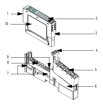
- Figure 1/2: Shows module parts including locking mechanism, RTB, and DIN rail screw.
- Figure 3: Status indicator layout for 1734-OW2 and 1734-OW4.
Model compatibility
- Compatible with DeviceNet, PROFIBUS, ControlNet, and EtherNet/IP adapters.
- 1734-OW4 and 1734-OW4K require external power; they cannot be powered from the internal power bus.

Manual page author
Michael Turner
Technical manual editor
Reviews PDF manuals for structure, safety notes, and practical product details so readers can find the right information quickly.