Industrial / I/O Modules
Installation Manual for Allen-Bradley 1792-IB16LP ArmorBlock-LP 16 Input Module
Quick installation and configuration guide for the Allen-Bradley 1792-IB16LP ArmorBlock-LP 16 Input Module. Includes wiring diagrams, mounting dimensions, indicator status definitions, and technical specifications.
Quick answers from the manual
Quick answer
- The 1792-IB16LP is a sealed I/O block module requiring no enclosure. It communicates via DeviceNet and is configured using DeviceNet Manager Software. p. 1
Key actions
- Set node address and baud rate p. 2
- Mount the module p. 3
Problems and fixes
Network Status (NS) Flashing Red
At least 1 I/O connection is in the timed-out state
p. 8
Module Status (MS) Solid Red
Critical failure
p. 8Technical specifications
| Parameter | Value | Meaning | Pages |
|---|---|---|---|
| Inputs | 16 sinking | Number and type of inputs | p. 9 |
| Enclosure | IP67 | Ingress protection rating | p. 10 |
Where to find it in the PDF
- Installation and Overview p. 1, 2
- Mounting and Wiring p. 3, 4, 5
- Troubleshooting and Specs p. 7, 8, 9, 10
Table of contents
Manual images
Click an image to enlargeQuick guide from the manual
This manual provides installation and configuration instructions for the 1792-IB16LP ArmorBlock-LP 16 Input Module. The module is a sealed I/O block that requires no enclosure and is compatible with PLC or SLC programmable controllers using DeviceNet scanners.
Installation
Installation consists of setting the node address and communication rate, mounting the module, connecting the wiring, and establishing communication. The module comes pre-set to node address 63 and a communication rate of 125Kbps. To change these settings, you need a host computer with DeviceNet Manager Software (or similar) and a 1770-KFD RS-232 module.
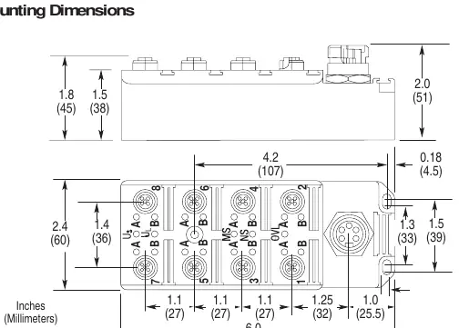
Mounting
Mount the block module directly to the machine or device. Use three #8 (4mm) screws to secure the block. Refer to the mounting dimensions diagram for exact spacing and clearance requirements.
Wiring
The module uses quick-disconnect, screw-on style connectors for I/O input and DeviceNet connections. Ensure all connectors are securely tightened to maintain IP67 requirements. Seven micro plugs are included to seal unused ports.
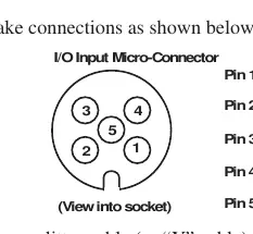
I/O Input Wiring
Connect input wiring to the micro-connectors on the front of the block. Pinout: Pin 1 = Sensor Source Voltage Positive, Pin 2 = Signal B, Pin 3 = Negative/Return, Pin 4 = Signal A, Pin 5 = Ground.
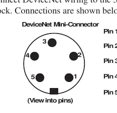
DeviceNet Wiring
Connect DeviceNet wiring to the 5-pin mini-connector on the end of the block. Pinout: Pin 1 = Drain (Bare), Pin 2 = V+ (Red), Pin 3 = V- (Black), Pin 4 = CAN-HI (White), Pin 5 = CAN-LO (Blue).
Communication
The module exchanges I/O with the master through Polled, Bit Strobe, or Change of State connections. The module consumes 0 bytes and produces 3 bytes in all connection types.
Troubleshooting
Use the status indicators to diagnose the module:
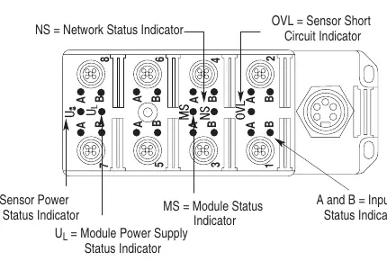
- NS (Network Status): Indicates network connection status.
- MS (Module Status): Indicates module health.
- OVL (Sensor Short Circuit): Solid red indicates one or more sensor source voltage shorts.
- US/UL (Power Status): Green indicates power supply is operating.
- A/B (Input I/O Status): Yellow indicates a valid input signal is present.
Specifications
The module features 16 sinking inputs with an on-state voltage range of 12-30V DC. It operates in temperatures from 0 to 60°C (32 to 140°F) and meets IP67 enclosure standards.
Manufacturer information
Allen-Bradley
Practical help
Common problems
Module not communicating
Check node address and baud rate settings using DeviceNet Manager Software. Ensure the 1770-KFD module is correctly connected.
Sensor short circuit detected
Check the OVL indicator. If solid red, identify and fix the short in the sensor or sensor cable.
No power indication
Check US and UL indicators. If off, verify the power supply is functioning and connected correctly.
Before use
- Verify DeviceNet Manager Software is installed on the host computer
- Ensure 1770-KFD RS-232 module is available for configuration
- Check for #8 (4mm) mounting screws
- Confirm power supply voltage is within 11-25V DC range
- Ensure all connectors are tightened to maintain IP67 seal
Images and diagrams
- System setup diagram shows connection from host computer to module via 1770-KFD
- Mounting dimensions diagram provides hole spacing and module size
- Connector pinouts detail wiring for I/O and DeviceNet
Model compatibility
- Compatible with PLC or SLC programmable controllers using DeviceNet scanners
- Requires DeviceNet Manager Software (cat. no. 1787-MGR) or similar for configuration

Manual page author
Emily Carter
User documentation editor
Prepares concise manual descriptions and highlights the most useful setup, operation, and maintenance information for readers.