Industrial / I/O Modules
Installation Instructions for Allen-Bradley POINT I/O Input Modules
A comprehensive installation and wiring guide for Allen-Bradley POINT I/O Input Modules (1734-IB2, 1734-IB4, 1734-IB4K, 1734-IB8, 1734-IB8K). Includes step-by-step mounting instructions, wiring diagrams for sink inputs, status indicator...
Quick answers from the manual
Quick answer
- The POINT I/O Input Modules are installed by mounting the base on a DIN rail, setting the keyswitch, inserting the module, and wiring the Removable Terminal Block (RTB). Ensure power is off before any installation or wiring activity. p. 5, 6, 7, 8
Key actions
- Mounting the base p. 6
- Installing the module p. 6
- Wiring the module p. 8, 9, 10
First start
- Ensure power is off, mount the base, set the keyswitch, insert the module, and wire the RTB. p. 6, 7, 8
Problems and fixes
Module status LED flashing red
Recoverable fault; check configuration.
p. 13
Network status LED flashing red
One or more I/O connections are in timed-out state.
p. 13Maintenance and reset
- Use a soft dry anti-static cloth to wipe down equipment. Do not use any cleaning agents. p. 4
Technical specifications
| Parameter | Value | Meaning | Pages |
|---|---|---|---|
| Voltage, on-state, nom | 24V DC | Nominal operating voltage | p. 13 |
| Operating Temperature | -20 to +55 °C | Ambient temperature range | p. 14 |
Where to find it in the PDF
- Installation p. 5, 6, 7, 8
- Specifications p. 13, 14, 15
Table of contents
Manual images
Click an image to enlargeQuick Guide from the Manual
This document provides installation and wiring instructions for the Allen-Bradley POINT I/O Input Modules (1734-IB2, 1734-IB4, 1734-IB4K, 1734-IB8, 1734-IB8K). These modules are designed for industrial environments and must be mounted in a suitable enclosure (IP54 minimum for hazardous locations). Always ensure power is removed before installing or removing modules to prevent electrical arcing.
Installation
The system consists of a mounting base, the I/O module, and a Removable Terminal Block (RTB).
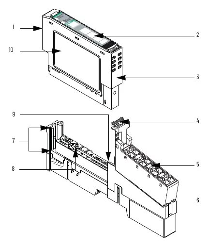

Mounting the Base
- Position the mounting base vertically above existing units.
- Slide the base down to engage the interlocking side pieces with the adjacent module.
- Press firmly to seat the base onto the DIN rail until it snaps into place.
Installing the Module
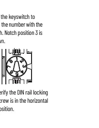
- Use a bladed screwdriver to rotate the keyswitch on the mounting base until the number corresponding to the module type aligns with the notch.
- Verify the DIN rail locking screw is in the horizontal position.
- Insert the module straight down into the mounting base and press to secure.
Installing the Removable Terminal Block (RTB)
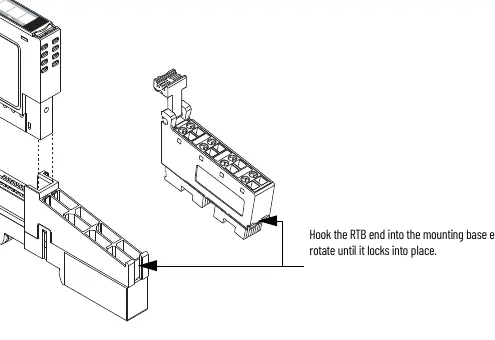
- Insert the end opposite the handle into the base unit.
- Rotate the terminal block into the wiring base until it locks.
- Snap the RTB handle into place on the module.
Wiring the Module
All wiring is connected to the Removable Terminal Block. These modules are sink inputs. Ensure you use the correct wiring diagram for your specific model (1734-IB2, 1734-IB4, or 1734-IB8).
- 2-Wire Proximity Switches: Connect according to the specific channel/common/voltage pinout provided in the manual.
- 3-Wire Proximity Switches: Connect common on 3-wire switches. 12/24V DC is supplied through the internal power bus.
- Daisy Chaining: Common and power connections can be daisy-chained from the adapter, 1734-FPD, 1734-EP24DC, or an external auxiliary terminal block.
Status Indicators
The modules feature LED indicators to help diagnose operation:
- Module Status: Green (normal), Flashing Green (needs configuration), Flashing Red (recoverable fault), Red (unrecoverable fault).
- Network Status: Green (online with connections), Flashing Green (online, no connections), Red (critical link failure).
- I/O Status: Yellow (input on), Off (input off).
Technical Specifications
Key operating parameters include:
- Voltage: 24V DC nominal (10...28.8V DC range).
- Input Filter Time: 0.5 ms hardware plus 0...63 ms (user-selectable).
- Operating Temperature: -20 to +55 °C (-4 to +131 °F).
- Isolation Voltage: 50V (continuous), Reinforced Insulation Type.
Manufacturer information
Allen-Bradley
Practical help
Common problems
Module status LED is solid red
This indicates an unrecoverable fault; the device may require replacement.
Electrical arcing during installation/removal
Ensure backplane power is removed or the area is nonhazardous before inserting or removing the module.
Improper grounding
Use zinc-plated chromate-passivated steel DIN rail to ensure proper grounding through the chassis.
Before use
- Verify power is removed before installation.
- Ensure the DIN rail is zinc-plated steel.
- Set the keyswitch on the mounting base to the correct position for the module.
- Verify the enclosure meets IP54 requirements if used in hazardous locations.
- Check that all external connections are secured.
Specs in practice
- Voltage, on-state, nom
- 24V DC is the standard operating voltage for inputs.
- Input filter time
- The time delay from a valid signal to recognition; adjustable from 0.5ms to 63.5ms.
- Power dissipation
- Heat generated by the module; varies by model (0.7W to 1.6W).
Images and diagrams
- Wiring diagrams illustrate connections for 2-wire and 3-wire proximity switches to the sink inputs.
- The diagrams show how to connect common and voltage (V) pins for different module types.
Model compatibility
- Compatible with 1734-TB or 1734-TBS mounting bases.
- Compatible with DeviceNet, PROFIBUS, ControlNet, and EtherNet/IP adapters.
- Requires RSLogix 5000 v11+ or Studio 5000 Logix Designer v20+.

Manual page author
David Miller
Documentation analyst
Organizes user manual content into clear summaries, with attention to model details, product context, and everyday usability.