Industrial / I/O Modules
Installation Instructions for Allen-Bradley POINT I/O Analog Input Modules
Comprehensive installation and wiring guide for Allen-Bradley POINT I/O 2 Current and 2 Voltage Input Analog Modules (1734-IE2C, 1734-IE2CK, 1734-IE2V, 1734-IE2VK). Includes mounting procedures, wiring diagrams, status indicator...
Quick answers from the manual
Quick answer
- The 1734-IE2C and 1734-IE2V are POINT I/O analog input modules. Installation involves mounting the base on a DIN rail, setting the keyswitch, inserting the module, and attaching the Removable Terminal Block (RTB). Wiring must follow the specific diagrams provided for current or voltage inputs. p. 6, 7, 8, 9
Key actions
- Mounting the base p. 6
- Installing the module p. 7
- Wiring the module p. 8, 9
First start
- Ensure the keyswitch is aligned with the notch for the specific module type before insertion. p. 6, 7
Problems and fixes
Module Status LED is red
Unrecoverable fault occurred (checksum failure, ram test failure, or firmware fatal error).
p. 10
Network Status LED is flashing green
Device is online but has no connections in the established state.
p. 10Maintenance and reset
- Use a soft dry anti-static cloth to wipe down equipment. Do not use any cleaning agents. p. 4
Technical specifications
| Parameter | Value | Meaning | Pages |
|---|---|---|---|
| Input Current (1734-IE2C) | 4...20 mA / 0...20 mA | Supported current input ranges. | p. 11 |
| Input Voltage (1734-IE2V) | 0...10V / ±10V | Supported voltage input ranges. | p. 11 |
Where to find it in the PDF
- Installation Instructions p. 6, 7
- Wiring Diagrams p. 9
- Specifications p. 11, 12
Table of contents
Manual images
Click an image to enlargeQuick guide from the manual
This document provides installation and configuration instructions for the Allen-Bradley POINT I/O 2 Current and 2 Voltage Input Analog Modules. These modules are designed for industrial environments and require specific mounting and wiring procedures to ensure safety and proper operation.
Safety and Environment
- Hazardous Locations: Equipment is suitable for Class I, Division 2, Groups A, B, C, D locations. Ensure power is removed before disconnecting equipment or wiring.
- Electrostatic Discharge: The equipment is sensitive to ESD. Use a grounded wriststrap and touch a grounded object before handling.
- Enclosure: Must be mounted in a suitable enclosure (minimum IP54 for Zone 2) accessible only by tool.
Installation
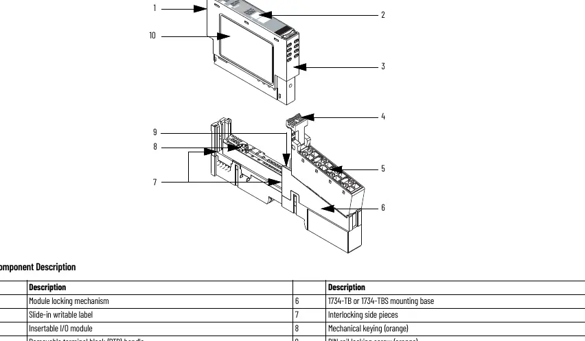
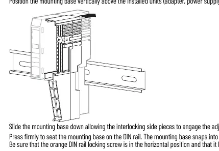

Mounting the Base
- Position the mounting base vertically above existing units.
- Slide the base down to engage interlocking side pieces.
- Press firmly to seat on the DIN rail. Ensure the orange DIN rail locking screw is in the horizontal position.
Installing the I/O Module
- Use a bladed screwdriver to rotate the keyswitch on the mounting base until the number required for the module aligns with the notch.
- Verify the DIN rail locking screw is horizontal.
- Insert the module straight down into the mounting base until it locks.
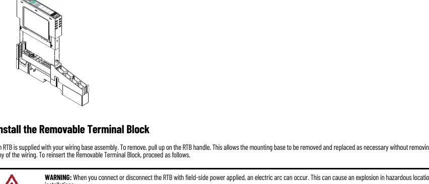
Installing the Removable Terminal Block (RTB)
- Insert the end opposite the handle into the base unit.
- Rotate the terminal block into the wiring base until it locks.
- Snap the RTB handle into place on the module.
Wiring
Refer to the specific wiring diagrams for your module type (Current Input 1734-IE2C or Voltage Input 1734-IE2V). Ensure all connections are secure. The modules use a 12/24V DC supply provided by the internal field power bus.
Status Indicators
The modules feature Module Status and Network Status LEDs to assist in troubleshooting:
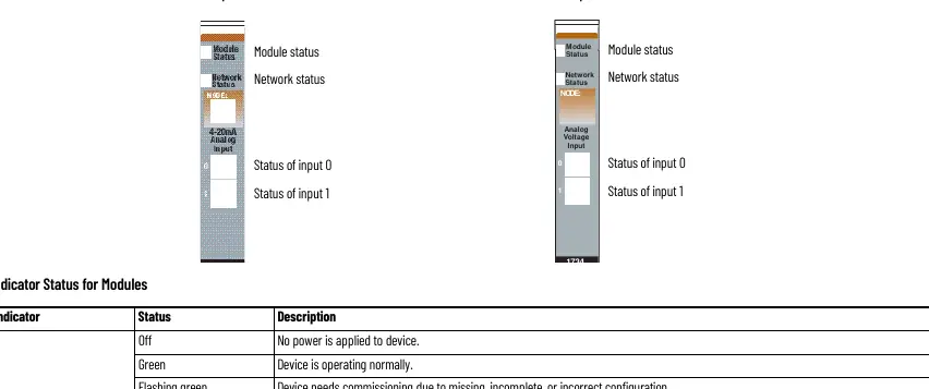
- Module Status: Green (Normal), Flashing Green (Needs commissioning), Flashing Red (Recoverable fault), Red (Unrecoverable fault).
- Network Status: Green (Online with connections), Flashing Green (Online, no connections), Red (Critical link failure).
Technical Specifications
The modules support 2 single-ended, non-isolated inputs. Current modules (1734-IE2C) support 4...20 mA and 0...20 mA. Voltage modules (1734-IE2V) support 0...10V or ±10V. Both feature Delta Sigma conversion and factory calibration.
Manufacturer information
Allen-Bradley
Practical help
Common problems
Module Status LED is flashing red
A recoverable fault is present. Check configuration and connections.
Network Status LED is red
Critical link failure. The device has detected an error preventing network communication.
Cannot insert module into base
Ensure the DIN rail locking screw is in the horizontal position and the keyswitch is correctly aligned.
Before use
- Ensure the DIN rail is zinc-plated chromate-passivated steel for proper grounding.
- Verify the keyswitch on the mounting base is set to the correct position for the module.
- Ensure power is removed before installing or removing modules/wiring.
- Use a static-safe workstation and wear a grounding wriststrap.
- Verify the enclosure meets IP54 requirements if used in Zone 2 environments.
Images and diagrams
- Wiring diagrams show connections for current input devices (2-wire/4-wire) and voltage input devices.
- Diagrams identify pinouts for Input 0, Input 1, Chassis Ground, Common, and Supply (V).
Model compatibility
- Compatible with DeviceNet, PROFIBUS, ControlNet, and EtherNet/IP adapters.
- Requires Studio 5000 Logix Designer version 20 or later for ControlNet/EtherNet/IP.

Manual page author
Emily Carter
User documentation editor
Prepares concise manual descriptions and highlights the most useful setup, operation, and maintenance information for readers.