Industrial / I/O Modules
Installation Instructions for Allen-Bradley 1734-IV2, 1734-IV4, 1734-IV8, and 1734-IV8K POINT I/O Source Input Modules
A comprehensive installation and wiring guide for Allen-Bradley 1734-IV2, 1734-IV4, 1734-IV8, and 1734-IV8K POINT I/O Source Input Modules. Includes mounting procedures, wiring diagrams, status indicator interpretation, and technical...
Quick answers from the manual
Quick answer
- This manual provides installation, wiring, and configuration instructions for Allen-Bradley 1734-IV2, 1734-IV4, 1734-IV8, and 1734-IV8K POINT I/O Source Input Modules. p. 1
Key actions
- Install Mounting Base p. 5
- Install Module p. 5
- Wire the Module p. 7, 8
Problems and fixes
Module status indicator flashing green
Device needs commissioning due to missing, incomplete, or incorrect configuration.
p. 11Technical specifications
| Parameter | Value | Meaning | Pages |
|---|---|---|---|
| Number of inputs (1734-IV2) | 2 | 1 group of 2 | p. 11 |
| Number of inputs (1734-IV4) | 4 | 1 group of 4 | p. 11 |
| Number of inputs (1734-IV8) | 8 | 1 group of 8 | p. 11 |
Where to find it in the PDF
- Installation p. 5, 6
- Specifications p. 11, 12
Table of contents
Manual images
Click an image to enlargeQuick guide from the manual
This document provides essential installation, wiring, and configuration instructions for the Allen-Bradley 1734-IV2, 1734-IV4, 1734-IV8, and 1734-IV8K POINT I/O Source Input Modules. Users must be trained personnel and comply with all applicable codes and standards. Important: Ensure power is removed or the area is non-hazardous before connecting or disconnecting any equipment to prevent electrical arcing and potential explosions in hazardous locations.
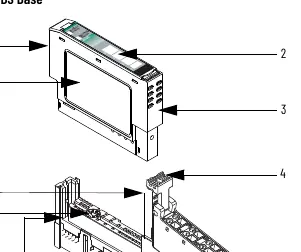
Installation
The system consists of a mounting base (1734-MB), a removable terminal block (RTB), and the I/O module.

Mounting Base Installation
- Position the mounting base vertically above existing units.
- Slide the base down to engage interlocking side pieces with adjacent modules.
- Press firmly to seat on the DIN rail. Ensure the orange DIN rail locking screw is in the horizontal position.
Module Installation
- Rotate the keyswitch on the mounting base clockwise until the number required for the module type aligns with the notch.
- Verify the DIN rail locking screw is horizontal.
- Insert the module straight down into the mounting base and press to secure.
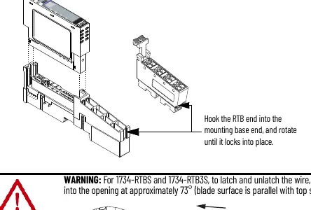
Removable Terminal Block (RTB)
- To remove, pull up on the RTB handle.
- To reinsert, hook the end opposite the handle into the base unit, rotate until it locks, and snap the handle into place.
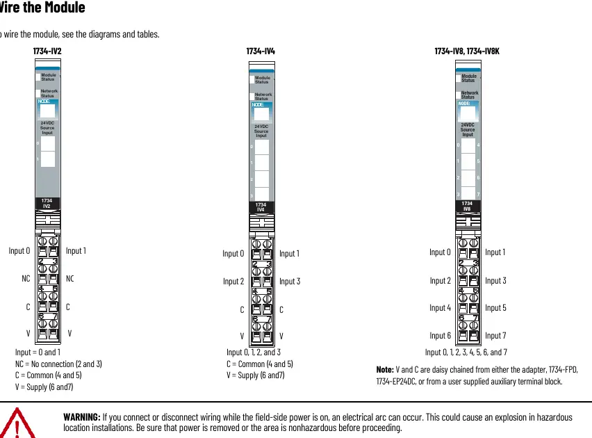
Wiring
Wiring diagrams are provided for each module type (1734-IV2, 1734-IV4, 1734-IV8/IV8K). Connections include input terminals, common terminals, and supply voltage. Ensure proper grounding via the DIN rail. For 3-wire proximity switches, connect power as indicated in the specific wiring diagrams.
Status Indicators
The module features status indicators for Module Status, Network Status, and Channel Status. A green Module Status light indicates normal operation, while flashing red indicates a recoverable fault. A red Network Status light indicates a critical link failure.
Technical Specifications
The modules operate within a temperature range of -20 to +55 °C (-4 to +131 °F). They are designed for Pollution Degree 2 industrial environments. Input voltage is 24V DC nominal (10-28.8V DC range). The input filter time is 0.5 hardware plus 0-63 ms (user selectable).
Manufacturer information
Allen-Bradley
Practical help
Common problems
Module status indicator flashing red
Recoverable fault; check configuration or device status.
Network status indicator red
Critical link failure; check network connections and communication settings.
Electrical arc during connection
Ensure power is removed or the area is non-hazardous before connecting/disconnecting.
Improper grounding
Ensure the DIN rail is zinc-plated chromate-passivated steel and properly grounded to chassis ground.
Before use
- Ensure power is removed before installation
- Verify DIN rail is grounded
- Check for hazardous location requirements
- Ensure correct keyswitch setting on mounting base
- Verify DIN rail locking screw is in horizontal position
Specs in practice
- Voltage, on-state
- 10V DC min, 24V DC nom, 28.8V DC max
- Input filter time
- 0.5 hardware plus 0-63 ms (user selectable)
- Isolation voltage
- 50V continuous, tested to 2500V DC for 60s
- Enclosure type rating
- None (open-style); must be mounted in a suitable enclosure
Images and diagrams
- Figure 1: External features of the POINT I/O module
- Figure 2-4: Wiring diagrams for 1734-IV2, 1734-IV4, and 1734-IV8/IV8K
- Figure 5-6: Wiring examples using 2-wire and 3-wire proximity switches
Model compatibility
- Compatible with DeviceNet and PROFIBUS adapters
- Compatible with ControlNet and EtherNet/IP adapters if using Studio 5000 Logix Designer version 20 or higher
- Must be used with UKEX/ATEX/IECEx certified Rockwell Automation backplanes

Manual page author
Michael Turner
Technical manual editor
Reviews PDF manuals for structure, safety notes, and practical product details so readers can find the right information quickly.