Industrial / I/O Modules
Installation Instructions for Allen Bradley FLEX I/O Power Supply Modules
A comprehensive installation and wiring guide for Allen Bradley FLEX I/O power supply modules (1794-PS13, 1794-PS13K, 1794-PS3, 1794-PS3K). Includes mounting procedures, wiring diagrams, diagnostic indicator explanations, and technical...
Quick answers from the manual
Quick answer
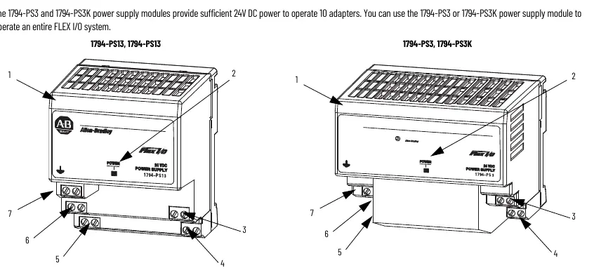
- These power supply modules provide 24V DC power for FLEX I/O systems. The 1794-PS13/K supports up to 4 adapters, while the 1794-PS3/K supports up to 10 adapters. p. 4
Key actions
- Mounting the module p. 5
- Wiring the module p. 6
Problems and fixes
Power indicator OFF
Check for no power, overvoltage (exceeded 35V DC), or overcurrent (above 1.4A for PS13 or 3.2A for PS3).
p. 7Maintenance and reset
- Overvoltage protection reset p. 8
Technical specifications
| Parameter | Value | Meaning | Pages |
|---|---|---|---|
| Input Voltage | 120V/230V AC | Nominal supply voltage | p. 8 |
| Output Voltage | 24V DC | Nominal output | p. 8 |
Where to find it in the PDF
- Installation p. 5
- Specifications p. 8
Table of contents
Manual images
Click an image to enlargeQuick Guide from the Manual
This document provides installation and wiring instructions for the Allen Bradley FLEX I/O power supply modules. These modules are designed for industrial environments and require specific mounting and wiring procedures to ensure safe operation. Key limitations include a maximum operating temperature of 55°C and specific adapter capacity limits (4 adapters for 1794-PS13/K, 10 adapters for 1794-PS3/K).
Environment and Enclosure
The equipment is intended for use in a Pollution Degree 2 industrial environment, in overvoltage Category II applications. It must be mounted within an enclosure that is suitably designed for the specific environmental conditions and provides protection against accessibility to live parts. The enclosure must have flame-retardant properties (5VA rating) and be accessible only by tool.
Preventing Electrostatic Discharge
The equipment is sensitive to electrostatic discharge (ESD). When handling, touch a grounded object to discharge potential static, wear an approved grounding wriststrap, and avoid touching connectors, pins, or circuit components. Store the equipment in static-safe packaging when not in use.
Installation
The power supply module is designed for DIN rail mounting:
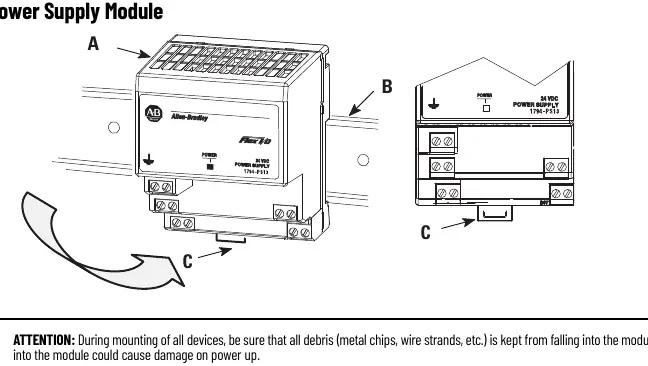
- Hook the lip on the rear of the module onto the top of the DIN rail.
- Rotate the module onto the rail.
- Press the module down until it is flush. The locking tab should snap into position.
- If it does not lock, use a screwdriver to move the locking tab down while pressing the module flush.
Wiring
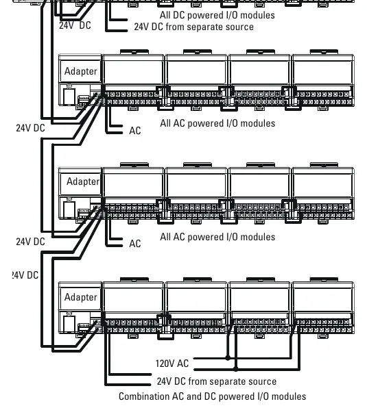
Ensure all wiring complies with applicable electrical installation requirements. Torque terminal screws to 0.8 N·m (7 lb·in). Connect 120/230V AC power to the left-side terminals (A, B, C). Connect 24V DC output to terminals G and H. Terminals I and J are used to daisy chain power to the next adapter in the series.
Diagnostic Indicator
The module features a single power indicator LED:
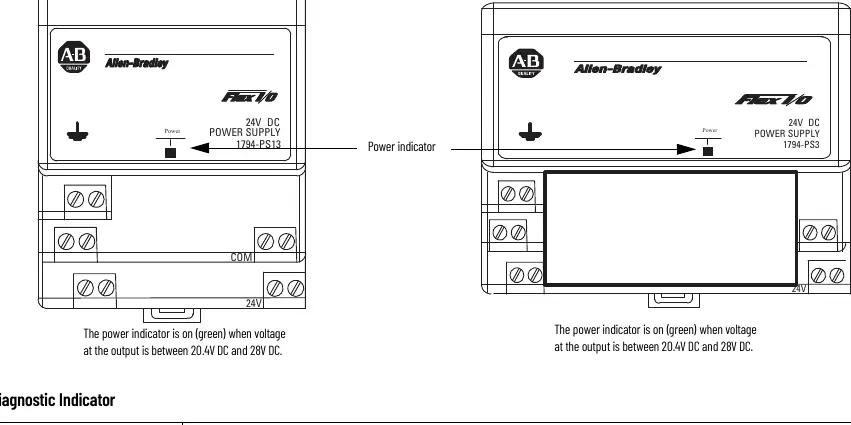
- ON (green): Output voltage is between 20.4V DC and 28V DC.
- OFF: No power applied, output voltage exceeded 35V DC (overvoltage protection), or output current exceeded the limit (1.4A for 1794-PS13/K; 3.2A for 1794-PS3/K).
Technical Specifications
The modules operate on 120V/230V AC input and provide 24V DC output. The 1794-PS13/K provides 31.2W of power, while the 1794-PS3/K provides 72W. Operating temperature range is 0 to 55°C.
Manufacturer information
Allen-Bradley
Practical help
Common problems
Module does not lock onto DIN rail
Use a screwdriver to move the locking tab down while pressing the module flush onto the rail.
Power indicator is OFF
Check if power is applied, if output voltage exceeded 35V DC (overvoltage protection), or if output current exceeded the rated limit.
Excessive noise or interference
Ensure the total length of wire for terminals H, I, J, and G does not exceed 3 meters (9.8 ft).
Before use
- Verify the environment is Pollution Degree 2.
- Ensure the DIN rail is zinc-plated chromate-passivated steel.
- Confirm power is removed before wiring or installation.
- Check that the enclosure provides adequate protection and flame retardancy.
- Ensure the ambient temperature is between 0 and 55°C.
Specs in practice
- Nominal Supply Voltage
- 120V AC or 230V AC, 50/60 Hz.
- Output Current (1794-PS13)
- 1.3 A maximum.
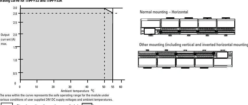
- Output Current (1794-PS3)
- 3 A (horizontal mounting) or 2.8 A (other mountings).
- Overvoltage Protection
- Output internally limited to 35V DC; cycle power to re-energize.
Images and diagrams
- Wiring diagram illustrates connections for AC power input and 24V DC distribution to adapters.
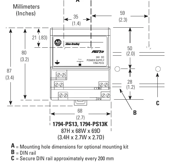
- Mounting dimensions provide clearance requirements for installation.
Model compatibility
- 1794-PS13/PS13K supports up to 4 adapters.
- 1794-PS3/PS3K supports up to 10 adapters.

Manual page author
Michael Turner
Technical manual editor
Reviews PDF manuals for structure, safety notes, and practical product details so readers can find the right information quickly.