Industrial / I/O Modules
Installation Instructions for Allen-Bradley FLEX I/O Digital Input/Output Modules
Comprehensive installation and configuration guide for Allen-Bradley FLEX I/O Digital Input/Output Modules (1794-IB10XOB6 and 1794-IB16XOB16P). Includes wiring diagrams, safety precautions, and technical specifications.
Quick answers from the manual
Quick answer
- This manual provides installation, wiring, and configuration instructions for Allen-Bradley FLEX I/O modules 1794-IB10XOB6 and 1794-IB16XOB16P. p. 1, 5, 6, 7
Key actions
- Mounting the module p. 5
- Wiring the module p. 5, 6, 7
First start
- Ensure power is off, mount on appropriate terminal base, connect wiring, and configure input filter time. p. 3, 5, 8
Maintenance and reset
- Use only a soft dry anti-static cloth to wipe down equipment. Do not use any cleaning agents. p. 3
Technical specifications
| Parameter | Value | Meaning | Pages |
|---|---|---|---|
| Operating Temperature | -20 to 55 °C (1794-IB10XOB6); 0 to 55 °C (1794-IB16XOB16P) | Safe operating temperature range. | p. 10 |
Where to find it in the PDF
- Installation p. 5
- Wiring 1794-IB10XOB6 p. 5, 6
- Wiring 1794-IB16XOB16P p. 6, 7
- Configuration p. 8
- Specifications p. 9, 10
Table of contents
Manual images
Click an image to enlargeQuick Guide from the Manual
This document provides installation, wiring, and configuration instructions for the Allen-Bradley FLEX I/O Digital Input and Output Modules, specifically models 1794-IB10XOB6 and 1794-IB16XOB16P. Always ensure power is removed before performing installation or wiring to prevent electrical arcs, especially in hazardous locations.
Environment and Enclosure
The equipment is intended for use in a Pollution Degree 2 industrial environment, in overvoltage Category II applications. It is supplied as open-type equipment and must be mounted within an enclosure that is suitably designed for the specific environmental conditions and prevents personal injury from accessibility to live parts. The enclosure must have flame-retardant properties and be accessible only by the use of a tool.
Installation
Follow these steps to install the module:
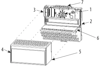
- Rotate the keyswitch on the terminal base clockwise to position 2.
- Ensure the Flexbus connector is pushed all the way to the left to connect with the neighboring terminal base/adapter.
- Verify that the pins on the bottom of the module are straight.
- Position the module with its alignment bar aligned with the groove on the terminal base.
- Press firmly and evenly to seat the module until the latching mechanism locks.
Wiring
Wiring connections differ based on the module model:
- 1794-IB10XOB6: Mounts on 1794-TB3 or 1794-TB3S terminal bases. Connect inputs and outputs to numbered terminals on row A, and power/common to rows B and C as specified in the wiring tables.
- 1794-IB16XOB16P: Mounts on 1794-TB32 or 1794-TB32S terminal bases. Follow the specific terminal assignments for inputs (IN0-IN15) and outputs (OUT0-OUT15) provided in the manual.
Important: Do not remove or replace a terminal base unit or adapter module while power is applied, as this can cause unintentional operation or machine motion.
Configuration
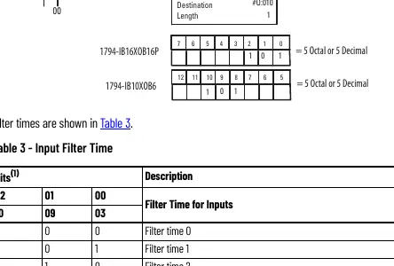
You can configure the module by setting bits in the configuration word (word 3). The input filter time can be adjusted to filter out noise or unwanted signals. Refer to the Input Filter Time table in the manual to select the appropriate filter time (ranging from 0.25 ms to 32 ms) by setting the corresponding bits.
Safety and Maintenance
The equipment is sensitive to electrostatic discharge. Always touch a grounded object or wear an approved grounding wriststrap when handling. Use only a soft dry anti-static cloth to wipe down the equipment; do not use cleaning agents.
Manufacturer information
Allen-Bradley
Practical help
Common problems
Module will not install
Ensure the Flexbus connector is pushed all the way to the left.
Improper grounding
Use zinc plated chromate-passivated steel DIN rail to ensure proper grounding.
Electric arc risk during installation
Ensure power is removed or the area is nonhazardous before inserting/removing the module or connecting wiring.
Before use
- Verify the environment is Pollution Degree 2.
- Ensure the DIN rail is zinc plated chromate-passivated steel.
- Confirm power is removed before installation or wiring.
- Check that the Flexbus connector is fully extended.
- Use an anti-static wriststrap when handling the module.
Specs in practice
- Input filter time
- Determines the delay for input signal recognition (0.25 ms to 32 ms).
- Isolation voltage
- 50V continuous, basic insulation type.
- Operating temperature
- -20 to 55 °C (1794-IB10XOB6) or 0 to 55 °C (1794-IB16XOB16P).
Images and diagrams
- Wiring diagrams show terminal assignments for inputs and outputs.
- Derating curve shows safe operating range based on ambient temperature and voltage.
Model compatibility
- 1794-IB10XOB6 mounts on 1794-TB3 or 1794-TB3S terminal bases.
- 1794-IB16XOB16P mounts on 1794-TB32 or 1794-TB32S terminal bases.

Manual page author
Emily Carter
User documentation editor
Prepares concise manual descriptions and highlights the most useful setup, operation, and maintenance information for readers.