Industrial / I/O Modules
Installation Instructions for Allen-Bradley FLEX I/O Digital DC Output Modules
Comprehensive installation and wiring guide for Allen-Bradley FLEX I/O Digital DC Output Modules (1794-OB8, 1794-OB8EP, 1794-OB16, 1794-OB16P, 1794-OB32P). Includes wiring diagrams, configuration, and specifications.
Quick answers from the manual
Quick answer
- The FLEX I/O Digital DC Output modules are installed by mounting them onto a 1794 terminal base with the keyswitch set to position 2. Wiring is connected to specific terminals based on the model and base unit. Faults on the 1794-OB8EP can be reset via the front button, software bit, or power cycling. p. 5, 8
Key actions
- Install module p. 5
- Reset fault (1794-OB8EP) p. 8
First start
- Set keyswitch to 2, ensure Flexbus connector is left, align module, and press firmly. p. 5
Problems and fixes
Fault indicator on 1794-OB8EP
Press reset button, toggle output reset bit, or cycle power.
p. 8Maintenance and reset
- Reset fault on 1794-OB8EP p. 8
Technical specifications
| Parameter | Value | Meaning | Pages |
|---|---|---|---|
| Number of outputs | 8, 16, or 32 | Depends on the specific module model. | p. 9, 10 |
Where to find it in the PDF
- Installation p. 5
- Specifications p. 9, 10, 11, 12
Table of contents
Quick Guide from the Manual
This document provides installation, wiring, and configuration instructions for the FLEX I/O Digital DC Output Modules. These modules are intended for use in Pollution Degree 2 industrial environments. Before installation, ensure the power is removed to prevent electric arcs, especially in hazardous locations. The modules must be mounted within a suitably designed enclosure.
Installation
To install the module on a 1794 terminal base:
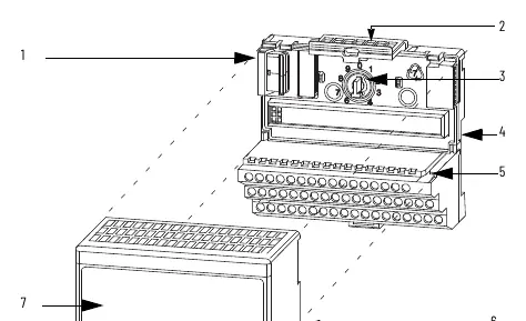
- Rotate the keyswitch on the terminal base to position 2.
- Ensure the Flexbus connector is pushed fully to the left.
- Align the module's alignment bar with the groove on the terminal base.
- Press the module firmly into the terminal base until the latching mechanism locks.
Wiring
Wiring connections vary by model and terminal base unit (e.g., 1794-TB2, 1794-TB3, 1794-TB32). Always connect individual output wiring to the specified row (A or B) and power/common to the specified terminals (C row). Total current draw through the terminal base is limited to 10A; separate power connections may be required for daisy-chaining.
Configuration
Modules are configured by setting bits in the configuration word. Refer to the Image Table Memory Map in the manual for specific bit assignments for your model (1794-OB8, 1794-OB8EP, 1794-OB16, 1794-OB16P, or 1794-OB32P).
Troubleshooting and Fault Reset
For the 1794-OB8EP module, faults can be reset in three ways:
- Press the fault reset button on the front of the module.
- Toggle the output reset bit (write word 1, bit 08).
- Cycle backplane power.
If the fault indicator turns off after pressing the reset button, the output will attempt to turn on after a short delay.
Safety and Environment
This equipment is sensitive to electrostatic discharge. Always use a grounded object or wriststrap when handling. Do not touch connectors or circuit components. Ensure the equipment is mounted in an enclosure with a minimum ingress protection rating of IP54 if used in Zone 2 environments.
Manufacturer information
Allen-Bradley
Practical help
Common problems
Fault indicator is on (1794-OB8EP)
Press the reset button, toggle the output reset bit, or cycle backplane power.
Module will not install
Ensure the Flexbus connector is pushed all the way to the left.
Before use
- Verify the environment is Pollution Degree 2.
- Ensure the DIN rail is zinc-plated chromate-passivated steel.
- Confirm power is removed before inserting or removing the module.
- Use a grounded wriststrap to prevent electrostatic discharge.
- Check that the keyswitch is set to position 2.
Specs in practice
- Isolation voltage
- 50V continuous, basic insulation type; tested at 850V DC.
- Output signal delay
- Time required for the output to switch from Off to On (0.1-0.5ms) or On to Off (0.1-1.0ms).
- Surge current
- Maximum repeatable current for 50ms, varies by model (2A to 4A).
Images and diagrams
- Wiring diagrams illustrate terminal connections for rows A, B, and C on various terminal bases.
- The derating curve shows the safe operating range for voltage and temperature.
Model compatibility
- Compatible with 1794 terminal bases (TB2, TB3, TB3S, TBN, TB32, TB32S).
- 1794-OB8EP requires 19.2...31.2V DC power range.

Manual page author
Emily Carter
User documentation editor
Prepares concise manual descriptions and highlights the most useful setup, operation, and maintenance information for readers.