Industrial / I/O Modules
Installation Instructions for Allen-Bradley FLEX I/O Analog Modules 1794-IE8, 1794-OE4, and 1794-IE4XOE2
Comprehensive installation and wiring guide for Allen-Bradley FLEX I/O analog modules 1794-IE8, 1794-OE4, and 1794-IE4XOE2. Includes mounting instructions, terminal base wiring diagrams, keyswitch settings, and technical specifications.
Quick answers from the manual
Quick answer
- This manual provides installation, wiring, and configuration instructions for Allen-Bradley FLEX I/O analog modules 1794-IE8, 1794-OE4, and 1794-IE4XOE2. It covers mounting, keyswitch settings, terminal base wiring, and technical specifications. p. 1, 4, 5
Key actions
- Set keyswitch to position 3 (1794-IE8), 4 (1794-OE4), or 5 (1794-IE4XOE2). p. 4
- Ensure Flexbus connector is fully extended to the left before mounting. p. 4
First start
- Set keyswitch, ensure Flexbus connector is extended, mount module, and connect wiring. p. 4, 5
Problems and fixes
Electrical arc risk
Remove power before inserting/removing module or connecting/disconnecting wiring.
p. 3, 4Technical specifications
| Parameter | Value | Meaning | Pages |
|---|---|---|---|
| External DC Power | 24V DC nominal | Operating voltage range 10.5...31.2V DC | p. 11 |
| Operating Temperature | 0...55 °C | Operating temperature range | p. 11 |
Where to find it in the PDF
- Installation p. 4
- Specifications p. 10, 11
Table of contents
Manual images
Click an image to enlargeQuick Guide from the Manual
This document provides installation and wiring instructions for the Allen-Bradley FLEX I/O analog modules (1794-IE8, 1794-OE4, and 1794-IE4XOE2). Before proceeding, ensure you are familiar with all applicable codes, laws, and standards. Important: Always remove power before inserting or removing the module or connecting/disconnecting wiring to prevent electrical arcs, especially in hazardous locations.
Installation
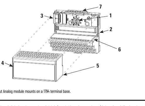
The module mounts on a 1794 terminal base. Follow these steps:

- Set Keyswitch: Rotate the keyswitch on the terminal base clockwise to the required position:
- 1794-IE8: Position 3
- 1794-OE4: Position 4
- 1794-IE4XOE2: Position 5
- Prepare Flexbus: Ensure the Flexbus connector is pushed all the way to the left to connect with the neighboring terminal base or adapter. The module cannot be installed unless the connector is fully extended.
- Mounting: Align the module's alignment bar with the groove on the terminal base. Press firmly and evenly until the latching mechanism locks.
Connecting Wiring
Wiring connections depend on the specific terminal base used (e.g., 1794-TB2, 1794-TB3, 1794-TB3S, 1794-TB3T, 1794-TB3TS, 1794-TBN). Use Belden 8761 cable for signal wiring.
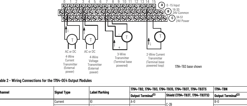
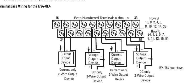
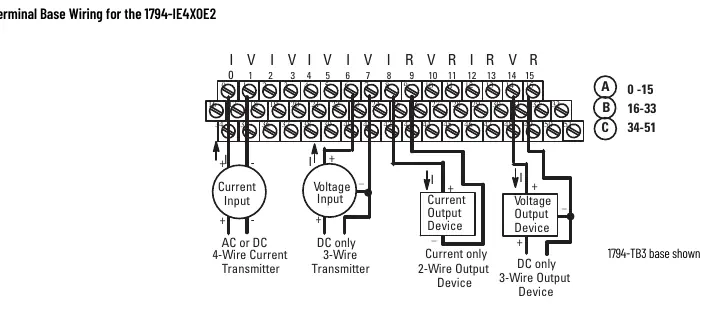
- Connect individual input/output wiring to the numbered terminals as specified in the wiring tables for your specific module.
- Connect signal wiring shields to functional ground as near as possible to the module.
- Connect +V DC power to terminal 34 and -V common/return to terminal 16 (refer to specific terminal base diagrams).
- To reduce noise, power analog and digital modules from separate power supplies. Do not exceed 9.8 ft (3 m) for DC power cabling.
Safety and Environment
This equipment is intended for use in a Pollution Degree 2 industrial environment. It is sensitive to electrostatic discharge (ESD). When handling, touch a grounded object, wear a grounding wriststrap, and avoid touching connectors or circuit components.
Technical Specifications
- External DC Power: 24V DC nominal (10.5...31.2V DC).
- Operating Temperature: 0 to 55 °C (32 to 131 °F).
- Isolation Voltage: Tested at 850V DC for 1 second.
- Flexbus Current: 15 mA.
Manufacturer information
Allen-Bradley
Practical help
Common problems
Module will not install on terminal base
Ensure the Flexbus connector is pushed all the way to the left. The module cannot be installed unless the connector is fully extended.
Electrical arc during installation/removal
Always remove power from the backplane and field side before inserting/removing the module or connecting/disconnecting wiring in hazardous locations.
Improper grounding
Use zinc-plated chromate-passivated steel DIN rail. Avoid aluminum or plastic rails as they can corrode or act as poor conductors.
Before use
- Verify the environment is Pollution Degree 2 industrial.
- Ensure power is disconnected before installation.
- Set the keyswitch to the correct position (3, 4, or 5) based on the module model.
- Check that the Flexbus connector is fully extended to the left.
- Use Belden 8761 cable for signal wiring.
- Ensure wire size is 22-12 AWG stranded copper.
Specs in practice
- Keyswitch Position
- Mechanical setting on the terminal base to ensure the correct module is installed (3=IE8, 4=OE4, 5=IE4XOE2).
- Operating Temperature
- The module must be operated within 0 to 55 °C (32 to 131 °F).
- Isolation Voltage
- Tested at 850V DC for 1 second between user power and system.
Images and diagrams
- Wiring diagrams illustrate the connection points for current/voltage transmitters and output devices on the terminal base.
- The keyswitch diagram shows the physical location on the terminal base that must be set before mounting.
Model compatibility
- Requires a 1794 terminal base.
- Not intended for residential environments.
- Must be mounted in an enclosure with at least IP54 rating for Zone 2 environments.

Manual page author
Michael Turner
Technical manual editor
Reviews PDF manuals for structure, safety notes, and practical product details so readers can find the right information quickly.