Lighting / LED Strips
Installation Instructions for American Lighting 120-H3 Series Hybrid 3 LED Tape
Quick guide for installing and maintaining American Lighting 120-H3 Series Hybrid 3 LED tape. Includes wiring instructions, cutting guidelines, mounting steps, and fuse replacement.
Table of contents
Manual images
Click an image to enlargeQuick Guide from the Manual
The American Lighting 120-H3 Series Hybrid 3 LED tape is designed for decorative lighting. Key operational requirements include a maximum run distance of 164 feet. The product must not be operated while coiled to prevent overheating. For outdoor installations, all connections, including end caps, must be sealed with dielectric grease and shrink tubing, and the circuit must be protected by a GFCI.
Safety Information
- Do not operate while coiled: This causes overheating and potential fire hazards.
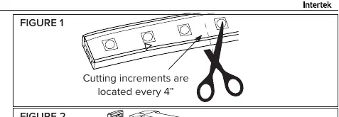
- Cutting: The product is wired in parallel with 4-inch cutting increments. Cutting outside these marks will damage the LEDs or wiring.
- Electrical Safety: Use only American Lighting recommended controllers, power connectors, and jumpers.
- Outdoor Use: Use only UL-approved outdoor extension cords (types SW, SOW, STW, STOW, SJW, SJOW, SJTW, or SJTOW).
- Polarized Plug: The plug is polarized; if it does not fit, reverse it. Do not force it or use an extension cord that does not allow full insertion.
Product Information
The Hybrid 3 Bulk Reels are sold in 150ft lengths. Each reel includes an attached 5ft removable power cord, four 120-H3-CONKITs, one removable end cap, and 50 mounting clips with screws. Power consumption is 4 W/ft.
Installation: Cutting
Determine the required length for the flexible light. Cut the Hybrid 3 squarely at the nearest cut mark using a sharp rope light cutting tool or shears. Ensure you only cut at the designated 4-inch increments.
Connecting Power
- Follow the cutting instructions to prepare the strip.
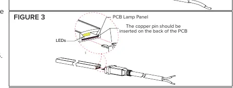
- Insert the rubber ring included with the conkit into the pin block side of the conkit.
- Insert the pin block into the Hybrid 3 strip.
- Press the pin block and Hybrid 3 into the connector’s pedestal, then place the cover over the pedestal.
- Screw down the lock screws to secure the conkit.
- Plug the 120V plug into an appropriate socket.
Linking with Splice Kit
- Prepare the strip ends as described in the cutting instructions.
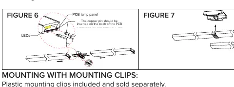
- Insert the pin block into the Hybrid 3 strip.
- Press the pin block and Hybrid 3 into the splice kit’s pedestal, then place the cover over the pedestal.
- Screw down the lock screws to secure the splice kit in place.
Mounting
Mounting Clips: Attach clips using nails or screws. Space them evenly, with a maximum of 12 inches apart. Ensure at least 1/2 inch distance between separate lines of Hybrid 3 to allow for heat distribution.
Mounting Channel: Attach the mounting track/channel to a mechanically sound surface using appropriate fasteners. Gently press the Hybrid 3 kit onto the track until it snaps into place.
Maintenance and Fuse Replacement
For cleaning, use a soft, dry or damp cloth. Do not use harsh chemicals or abrasives.
To Replace Fuse:
- Disconnect power before replacing the fuse.
- Grasp the plug and remove it from the outlet.
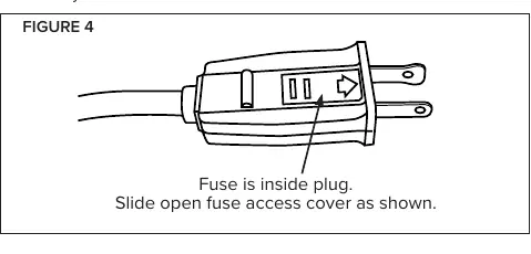
- Slide open the fuse access cover on the plug.
- Remove the old fuse carefully.
- Replace with an 8 Amp 125 Volt fuse only. Never use a higher wattage fuse.
- Close the fuse access cover.
Manufacturer information
American Lighting Inc.
Practical help
Common problems
Light overheating
Do not operate while coiled. Maintain at least 12mm spacing between flexible light cables.
Plug does not fit outlet
The plug is polarized. Reverse the plug and try again. Do not force it.
ETL Listing voided
The safety rating is void if the product is cut, altered, or used with non-recommended power cords.
Before use
- Ensure power is disconnected at the source before installation.
- Verify the total run length does not exceed 164 feet.
- Inspect the PVC housing and power cord for damage.
- Ensure you have dielectric grease and shrink tube for outdoor connections.
- Confirm the mounting surface is mechanically sound.
Specs in practice
- Power consumption
- 4 Watts per foot.
- Cutting increment
- The strip can only be cut every 4 inches.
Images and diagrams
- Figures 1-5 illustrate the process for connecting the power kit and linking jumpers.
- Figures 6-8 illustrate the process for using the splice kit.
- Figure 4 shows the location of the fuse access cover on the plug.
Model compatibility
- Use only American Lighting recommended controllers, power connectors, and jumpers.
- For outdoor use, use UL approved outdoor extension cords (SW, SOW, STW, STOW, SJW, SJOW, SJTW, or SJTOW).

Manual page author
David Miller
Documentation analyst
Organizes user manual content into clear summaries, with attention to model details, product context, and everyday usability.