Lighting / Outdoor Lighting
Installation Guide for Hinkley 16805 Hardy Island LED Deck Sconce
Step-by-step installation instructions for the Hinkley 16805 Hardy Island LED Deck Sconce. This guide covers mounting procedures, wiring requirements, and low-voltage cable safety guidelines.
Quick answers from the manual
Quick answer
- The Hinkley 16805 LED Deck Sconce requires a 9-15V AC power supply. Installation involves using the provided template to drill pilot holes, mounting the fixture with #6 screws, and connecting the wires to a low-voltage transformer. p. 1
Key actions
- Mounting the fixture p. 1
- Wiring the fixture p. 1
Technical specifications
| Parameter | Value | Meaning | Pages |
|---|---|---|---|
| Input Voltage | 9-15 Volts AC | Operating voltage range | p. 1 |
Where to find it in the PDF
- Installation Instructions p. 1
Table of contents
Manual images
Click an image to enlargeQuick guide from the manual
The Hinkley 16805 Hardy Island LED Deck Sconce is a low-voltage lighting fixture designed for outdoor use. It requires a 9-15V AC power supply. Installation involves using the provided template to drill pilot holes, mounting the fixture with #6 screws, and connecting the wires to a low-voltage transformer.
Luminaire Mounting
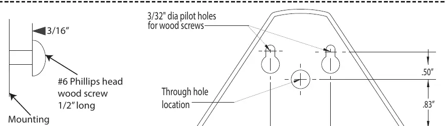
- Use the provided mounting template to mark and drill holes on the mounting surface.
- Drill pilot holes using a 3/32" diameter drill bit at the indicated points.
- Install #6 Phillips head wood screws, leaving a 3/16" gap between the screw head and the mounting surface.
- If wiring passes through the mounting surface, drill the hole as indicated on the template.
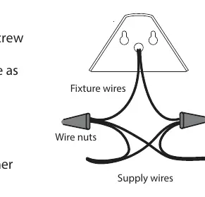
Luminaire Wiring
The fixture operates on 9-15 Volts AC. Connect both fixture wires to the supply wires from the transformer using wire nuts.
Low Voltage Cable Requirements
- Route the main low voltage cable in close proximity to the luminaire or building structure.
- The cable should not be buried, except for a maximum of 6 inches (15.2 cm) to connect to the main cable.
- Ensure the cable is cut and connected to a connector within 6 inches (15.2 cm) of a building structure, luminaire, or fitting.
Manufacturer information
Hinkley Lighting
Practical help
Common problems
Fixture does not light up
Verify that the input voltage is between 9-15 Volts AC and that all wire connections are secure.
Difficulty mounting the fixture
Ensure the mounting template is used to mark holes and that a 3/32" drill bit is used for pilot holes.
Before use
- Verify transformer output is 9-15V AC
- Ensure mounting surface is suitable for screw installation
- Have #6 Phillips head wood screws ready
- Check cable routing path for compliance with burial limits
Specs in practice
- Input Voltage
- 9-15 Volts AC required for operation
- Pilot Hole Size
- 3/32 inch diameter drill bit required
Images and diagrams
- The wiring diagram illustrates connecting fixture wires to supply wires using wire nuts.
- The mounting diagram shows the pilot hole locations and the required 3/16 inch gap for the screw head.
Model compatibility
- Requires a low voltage transformer providing 9-15V AC.

Manual page author
Emily Carter
User documentation editor
Prepares concise manual descriptions and highlights the most useful setup, operation, and maintenance information for readers.