Power / Uninterruptible Power Supplies
User Manual for APC Back-UPS Pro 1300G/1500G
Comprehensive user guide for the APC Back-UPS Pro 1300G and 1500G. Includes setup instructions, battery connection, software installation, operation modes, troubleshooting, and system fault codes.
Table of contents
Manual images
Click an image to enlargeQuick Start Guide
Before using your APC Back-UPS Pro, ensure you have inspected the package for damage and read the separate Safety Guide. The most critical initial step is connecting the internal battery.

- Connect the Battery: Open the battery compartment, slide the battery out, rotate it 180 degrees, slide it back in, and secure the cover.
- Power Connection: Connect the UPS power cable directly to a wall outlet. Do not use surge protectors or extension cords.
- Software: To use PowerChute Personal Edition for automatic shutdown, connect the supplied USB cable to your computer. Download the software from www.apc.com/pcpe.
Device Overview
The Back-UPS Pro features various outlets on the rear panel:
- Battery Backup with Surge Protection: Provides power during outages. Connect critical equipment like computers and monitors here.
- Surge Protection Only: Provides full-time surge protection but no battery backup. Connect printers or scanners here.
- Master and Controlled Outlets: The Master outlet detects if the main device (e.g., computer) is in sleep/standby mode and automatically shuts down the Controlled outlets to save energy.
Operation and Configuration
Power Saving Function
The Power Saving feature allows the UPS to shut down peripheral devices when the Master device is off or in sleep mode. To enable or disable this, press and hold MUTE and DISPLAY simultaneously for two seconds. To set the threshold, connect your master device, put it in sleep mode, then press DISPLAY and MUTE simultaneously for six seconds until the leaf icon flashes.
Unit Sensitivity
You can adjust the sensitivity to control when the UPS switches to battery power. With the unit connected to power but turned OFF, press and hold the POWER button for six seconds. The LOAD CAPACITY bar will flash. Press POWER again to cycle through Low, Medium (Default), and High sensitivity settings.
Display and Indicators
The front panel display provides real-time status:
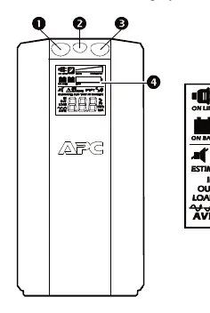
- On Line: Supplying conditioned utility power.
- Load Capacity: Shows the current load in 20% increments.
- Battery Charge: Indicates remaining battery capacity.
- Automatic Voltage Regulation (AVR): Indicates the unit is compensating for high or low input voltage.
- System Faults: If an icon appears, refer to the System Faults section.
Troubleshooting and Faults
If the UPS encounters an issue, it will display a fault code (F01-F09). For faults F01 and F02, turn the unit off, disconnect non-essential equipment, and turn it back on. For faults F03-F09, contact APC Technical Support. Common issues like the unit not switching on often relate to the battery not being connected or a tripped circuit breaker.
Maintenance
The battery typically lasts three to five years. When the REPLACE BATTERY indicator illuminates, the battery is nearing the end of its life. The replacement part for both models is APCRBC124. Always deliver used batteries to a recycling facility.
Official resources from the manual
Practical help
Common problems
Back-UPS will not switch on
Ensure it is connected to a wall outlet, check if the circuit breaker tripped, or verify the internal battery is connected.
No power during utility outage
Ensure essential equipment is not plugged into a 'SURGE ONLY' outlet; move it to a 'Battery Backup' outlet.
REPLACE BATTERY indicator is illuminated
The battery has reached the end of its useful life. Replace with part number APCRBC124.
OVERLOAD indicator is illuminated
The connected equipment is drawing more power than the UPS can provide. Disconnect non-essential items.
Before use
- Inspect package contents for damage upon receipt.
- Read the separate Safety Guide before installation.
- Connect the internal battery (see page 1 of the manual).
- Connect the UPS power cable directly to a wall outlet.
- Do not use surge protectors or extension cords with the UPS.
Specs in practice
- Maximum Load
- 780 W / 865 W maximum power output.
- Transfer Time
- 8 ms maximum; the time taken to switch to battery power.
- Typical Recharge Time
- 8 hours to fully recharge the battery.
Images and diagrams
- The rear panel diagram identifies battery backup outlets, surge-only outlets, and the master/controlled outlet configuration.
- The front panel diagram explains the buttons (Mute, Power, Display) and the LCD interface icons.
Model compatibility
- PowerChute Personal Edition software is compatible with Windows operating systems only.
- External battery pack connector is for Back-UPS RS 1500 model only.

Manual page author
Michael Turner
Technical manual editor
Reviews PDF manuals for structure, safety notes, and practical product details so readers can find the right information quickly.