Computers / Laptops
Disassembly Guide for Apple Macintosh 128K
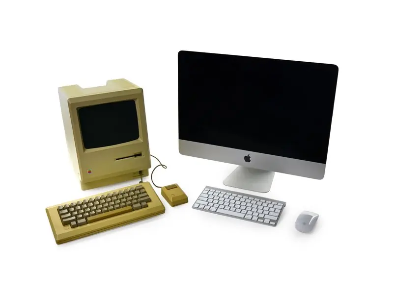
A comprehensive disassembly guide for the classic Apple Macintosh 128K. Learn how to safely open the case, remove the power supply, CRT display, logic board, and peripherals with step-by-step instructions.
Table of contents
Manual images
Click an image to enlargeQuick guide from the manual
This guide provides instructions for the teardown of the original 1984 Apple Macintosh 128K. Please note that this device contains high-voltage components, specifically within the CRT display and power supply, which can be hazardous if mishandled. Always exercise extreme caution.
Tools required
- T15 Torx Screwdriver
- Phillips #1 Screwdriver
- Flathead Screwdriver
- Spudger
Disassembly procedures
Opening the case
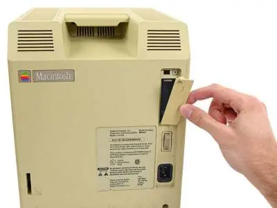
The case is secured by deeply recessed screws. Use a T15 Torx screwdriver with a flex extension to access these screws. One screw is hidden under the clock battery door. Once the screws are removed, use a spudger to carefully separate the case panels.
Removing the power supply
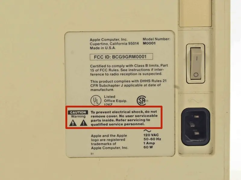
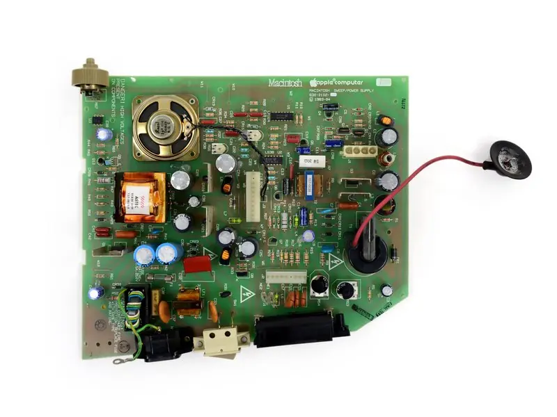
After opening the case, the power supply unit is accessible. Disconnect the power supply carefully, treating it as a high-voltage component. The 60-watt power supply (Apple Part number 630-0102) can then be removed.
Logic board removal
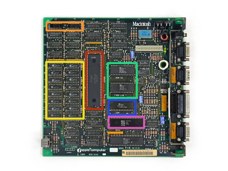
The logic board is located beneath the CRT and floppy drive assembly. It slides neatly out of its tray once the surrounding components are cleared. Note that the RAM on the logic board is soldered and cannot be upgraded.
Keyboard and mouse
The keyboard can be opened by removing a few screws, though the mechanical buttons are soldered to the board. The mouse can be disassembled by popping out the ball with a quick twist, revealing the internal quadrature encoders and resistors.
Repairability and maintenance
The Macintosh 128K has a repairability score of 7 out of 10. Once the case is opened, it is relatively straightforward to replace main components like the floppy drive, power supply, logic board, or CRT display. There is no adhesive used in the construction, and the clock battery is user-replaceable. However, the case is difficult to open due to the tight fit and recessed screws, and high-voltage hazards remain a significant concern for DIY repairs.

Manufacturer information
Apple Inc.
Practical help
Common problems
Case is difficult to open
Use a T15 Torx screwdriver with a flex extension to reach the deeply recessed screws.
High voltage hazard
Exercise extreme caution when handling the CRT display and power supply capacitors; they can retain dangerous charges.
Limited upgradability
The RAM is soldered to the logic board and cannot be replaced. Storage expansion is only possible via an optional external floppy drive.
Before use
- T15 Torx Screwdriver
- Phillips #1 Screwdriver
- Flathead Screwdriver
Specs in practice
- Power Supply
- 60-watt unit (Apple Part 630-0102)
Images and diagrams
- Logic board component layout
- Power supply unit connections
- Mouse internal mechanism
Model compatibility
- RAM is non-upgradable
- Keyboard cable uses a standard RJ9 connector but with custom pin wiring; standard phone cords will not work.

Manual page author
David Miller
Documentation analyst
Organizes user manual content into clear summaries, with attention to model details, product context, and everyday usability.