Electronics / Networking
Status Indicators Guide for Arista 7050 Series 1RU Switches
Understand the LED status indicators for your Arista 7050 Series 1RU data center switch. This guide covers front panel switch and port LEDs, as well as rear fan and power supply status lights to help you monitor system health.
Quick answers from the manual
Quick answer
- The Arista 7050 Series 1RU switches use front and rear panel LEDs to indicate the status of the system, fans, power supplies, and network ports. Green generally indicates normal operation, while Amber, Yellow, or Red indicate faults or warnings. p. 2, 3, 4, 5
Key actions
- Check system status via CLI p. 5
First start
- System boot time p. 2
Problems and fixes
System Status LED is Amber/Yellow/Orange
Two or more fans are disconnected or malfunctioning; switch will execute a graceful shutdown.
p. 2Where to find it in the PDF
- Front Indicators p. 2
- Rear Indicators p. 3, 4, 5
Table of contents
Manual images
Click an image to enlargeQuick guide from the manual
This guide explains the LED status indicators for Arista 7050 Series 1RU data center switches. These indicators are located on both the front and rear panels and provide real-time feedback on the operational status of the system, fans, power supplies, and network ports.
Front Panel Indicators
The front panel LEDs are located on the right side of the chassis. Depending on your specific device configuration, they are labeled as shown in the device diagrams.
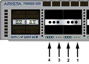
Switch Status LEDs
- System Status LED:
- Blinking Green: System is powering up (may take up to 10 minutes).
- Green: Normal operation.
- Blue / Blinking Blue: Locater function is active.
- Amber / Yellow / Orange: Two or more fans are disconnected or malfunctioning. The switch will execute a graceful shutdown.
- Fan Status LED:
- Green: All fan and power modules are operating normally.
- Amber / Yellow / Orange: Single fan module is removed, malfunctioning, or has a stuck rotor.
- Red: Two or more fans are disconnected or malfunctioning. The switch will execute a graceful shutdown.
- PSU [1:2] Status LED:
- Green: PSU is functioning and fully operational.
- Red: PSU removed, AC cord unplugged, stuck fan rotor, or internal fault.
Port Status LEDs
Port LEDs are located near their corresponding ports and indicate link and operational status. Behavior is consistent for both QSFP+ and SFP+ ports.
- Off: Port link is down.
- Green: Port link is up.
- Yellow / Orange / Amber: Port is software disabled.
- Flashing Yellow: Software controlled.
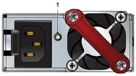
Rear Panel Indicators
Fan and power supply modules are accessed from the rear panel. Each module contains an LED reporting its specific status.
Fan Status LEDs
- Off: Fan module not detected or not seated properly.
- Green: Fan is operating normally.
- Red: Fan has failed.
Note: The handle or bezel color indicates the airflow direction.
Power Supply Status LEDs
Status conditions vary based on the specific power supply model (AC or DC). Generally, a Green light indicates normal operation with input power present. Yellow/Amber/Orange or Blinking Yellow typically indicates a power supply fault. If the light is Off, no input power supply is installed in the chassis.
For specific error conditions, you can log in to the switch and use the show environment commands to view the device state.
Practical help
Common problems
System Status LED is Amber/Yellow/Orange
This indicates two or more fans are disconnected or malfunctioning. The switch will automatically perform a graceful shutdown.
Fan Status LED is Red
Two or more fans are disconnected or malfunctioning. The switch will automatically perform a graceful shutdown.
PSU Status LED is Red
The PSU has been removed, the AC cord is unplugged, the fan rotor is stuck, or there is an internal fault.
Port LED is Off
The port link is down.
Before use
- Ensure all power cables are securely connected to the power supply modules.
- Verify that all fan modules are properly seated in the rear panel.
- Allow up to 10 minutes for the system to boot up and reach operational status.
- Check the handle or bezel color on fan modules to confirm airflow direction.
Images and diagrams
- Front panel LEDs are located on the right side of the chassis.
- Rear panel LEDs are located directly on the fan and power supply modules.
Model compatibility
- Port LED behavior is consistent for both QSFP+ and SFP+ ports.

Manual page author
Michael Turner
Technical manual editor
Reviews PDF manuals for structure, safety notes, and practical product details so readers can find the right information quickly.