Industrial / I/O Modules
User Manual for ACCES I/O 104-AIO12-8 Multifunction Analog I/O Board
Comprehensive user manual for the ACCES I/O 104-AIO12-8 multifunction board. This guide covers hardware installation, jumper configuration, register programming, and connector pin assignments for analog and digital I/O.
Table of contents
Manual images
Click an image to enlargeQuick Guide from the Manual
The 104-AIO12-8 is a PC/104 multifunction board. Warning: Always turn off computer power before installing or removing the board or connecting/disconnecting field cabling to prevent damage to the I/O board and voiding warranties.
- Installation: Configure jumpers for base address and options before installing the board into the PC/104 stack.
- Software: Install the provided software from the CD to access sample programs and the FINDBASE utility for address selection.
- Configuration: Use the Setup Program on the CD to assist with jumper settings.
Hardware Installation
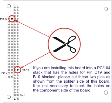
Before installing the board, read the manual to configure jumpers according to your requirements. If installing into a PC/104 stack with blocked holes for pins C19 and B10, you must cut these two pins from the solder side of the board.
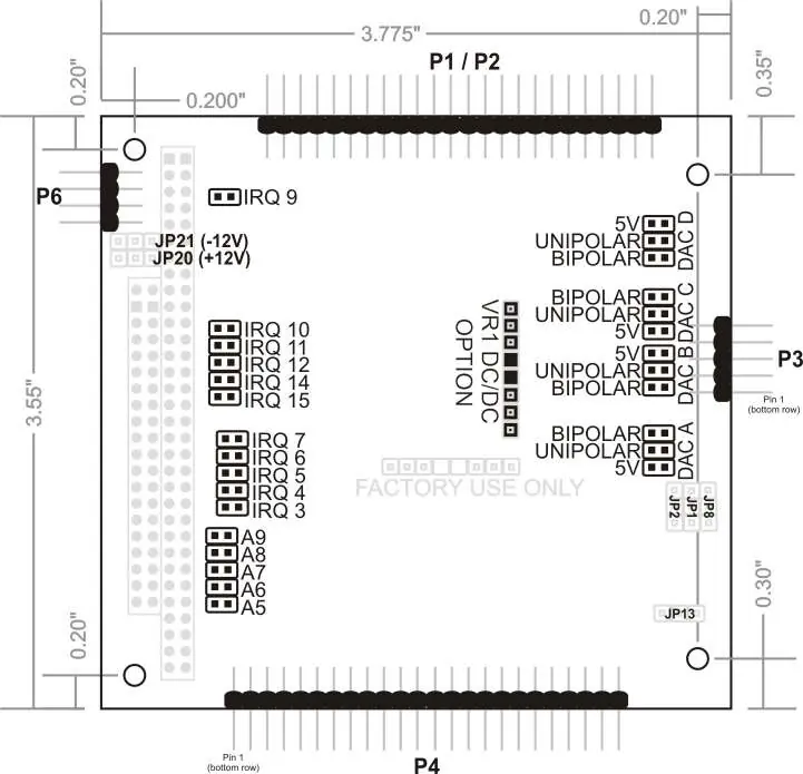
Option Selection and Jumpers
Jumpers are used to configure the base address (A5-A9), IRQ levels, DAC output voltage ranges, Digital I/O modes, and power options. The standard board supports most functionality, with factory options available for 4-20mA inputs, single-ended inputs, and DC/DC converters for +5V only operation.
Programming and Register Map
The board uses 24 consecutive registers in I/O space. Key registers include:
- Base + 0h: Board Status / Clear Board Status
- Base + 1h: Interrupt Enables / Status
- Base + 2h/3h: A/D Data
- Base + 4h-Bh: DAC Output
- Base + 10h-12h: Digital I/O Ports A, B, and C
- Base + 13h: Digital I/O Command Byte
- Base + 18h: DAC Reference Enable (required to enable DAC output)
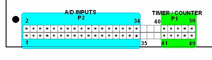
Connector Pin Assignments
The board features specific connectors for Analog I/O (P2/P1), Digital I/O (P4), and Power (P6). Refer to the pinout tables in the manual for specific signal connections, ensuring that you do not connect signal sources to instrumentation amplifier output pins.
Technical Specifications
The board features 8 true differential analog inputs (12-bit, 100k samples/sec), 4 analog outputs (12-bit), 24 digital I/O lines (82C55A), and 3 x 16-bit counter/timers (82C54). Operating temperature is 0 to +70°C standard, with an optional -40 to +85°C range.
Practical help
Common problems
Unpredictable computer behavior
Check for address conflicts using the FINDBASE utility provided on the CD.
DAC output is zero or random
Ensure Bit 0 at Base + 18h is set to enable the DAC reference. This must be done after every system reset.
Digital I/O lines go low when configured as output
Use TRISTATE mode (Base + 14h) to prevent low-going glitches during output configuration.
A/D conversion not working
Ensure the board is receiving proper power (+/-12V) either from the PC/104 bus or via P6.
Before use
- Power off the PC/104 stack.
- Configure jumpers for base address and IRQ.
- Install software from the provided CD.
- Verify address settings using FINDBASE.
- Check if pins C19 and B10 need to be cut for your specific stack.
- Ensure DAC reference is enabled in software.
Specs in practice
- 12-Bit Resolution
- Provides 4096 discrete levels for analog input and output values.
- Common Mode Rejection
- 86dB typical; allows the board to reject noise on differential input signals.
Images and diagrams
- Option Selection Map: Shows the physical location of jumpers for IRQ, address, and DAC ranges.
- PC/104 Key Information: Illustrates pin cutting requirements for specific stack configurations.
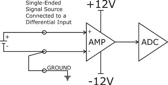
- Analog Input Wiring: Diagrams for connecting differential, single-ended, and 4-20mA sources.
- Connector Layout: Shows the pin arrangement for P1, P2, P3, and P4 connectors.
Model compatibility
- Compatible with PC/104 stack architecture.
- Requires +5V, +12V, and -12V power (or optional DC/DC converter for +5V only).
- Digital I/O is based on 8255 industry-standard configuration.

Manual page author
David Miller
Documentation analyst
Organizes user manual content into clear summaries, with attention to model details, product context, and everyday usability.