Industrial / I/O Modules
User Manual for Assured 104-DIO-48E and 104-DIO-24E Digital I/O Board
Quick guide for the Assured 104-DIO-48E and 104-DIO-24E digital I/O boards. Includes installation, jumper configuration, address selection, and programming examples.
Table of contents
Manual images
Click an image to enlargeQuick guide from the manual
The Assured 104-DIO-48E and 104-DIO-24E are industrial digital I/O boards designed for PC/104 bus sockets. They provide 48 bits of digital input/output, buffered lines, and optional 82C54 counter/timer functionality. These boards are compatible with industry-standard I/O racks like Opto-22 and Gordos.
Installation
Warning: Always turn off computer power before installing or removing the board. Connecting or disconnecting cables while the system is powered can damage the I/O board and void the warranty.
- Software Installation: Install the provided software from the CD before using the board. Follow the specific instructions for DOS, Windows, or Linux provided in the manual.
- Hardware Setup: Configure jumpers for the desired base address and IRQ level before mounting the board.
- Mounting: Assemble standoff hardware for stacking. Plug the board onto the PC/104 connector, ensuring proper pin alignment.
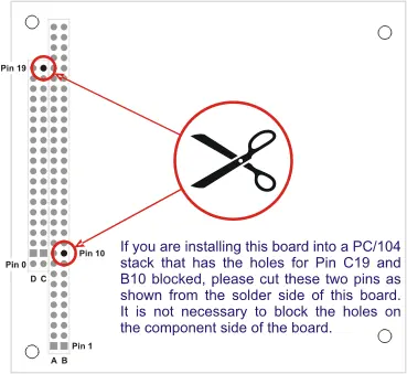
- Pin Modification: If installing into a PC/104 stack with blocked holes for Pin C19 and B10, cut these two pins from the solder side of the board.
Address Selection
The board occupies 16 bytes of I/O space. The base address is selectable via jumpers within the 000-3F0 hex range. Use the provided FINDBASE.EXE program to find an available address for your system to avoid conflicts.
Programming
The board is I/O-mapped. The recommended programming languages for interrupt service routines are Delphi or C++ Builder. Visual BASIC is not recommended for interrupt-type programming.
- Digital I/O: Uses two 8255-5 PPIs. Each 8-bit port can be configured as input or output.
- Counter/Timer: The optional 82C54 chip provides three 16-bit counters. It shares I/O space with PPI 0. To access it, write any value to base address + Dh. To return to DIO, read from base address + Dh.
- Interrupts: External interrupts are accepted on pin 9 (bit C3). Interrupts are directed to levels #2-#7 and #10-#12 via jumpers.
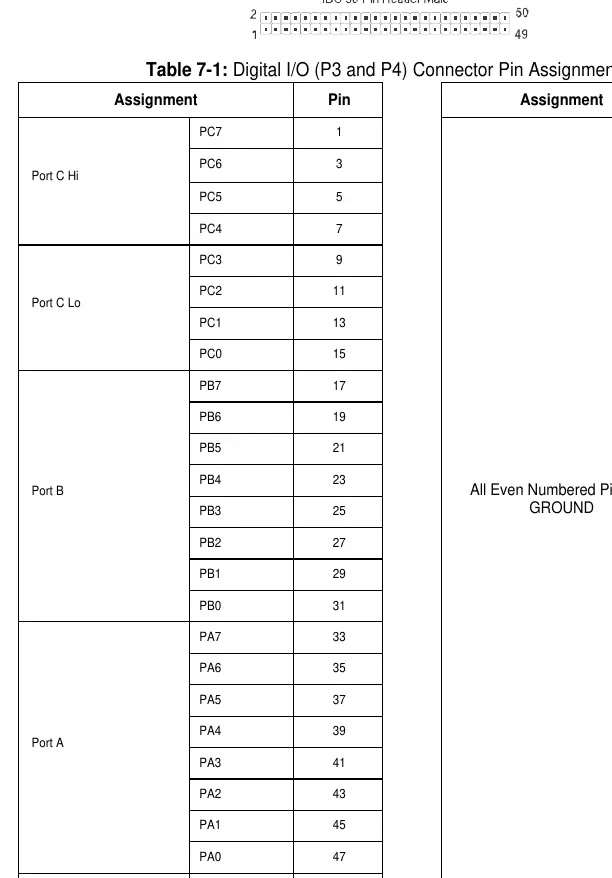
Connector Pin Assignments
The board features two 50-pin headers (P3 for Group 0, P4 for Group 1). Every second line is grounded to minimize crosstalk. Pin 49 provides +5 VDC power (resettable fuse).
Official resources from the manual
Practical help
Common problems
Unpredictable computer behavior
Check for overlapping I/O addresses with other installed functions.
Interrupts not functioning
Ensure a jumper is installed in the IEN or INP position and that the interrupt is cleared by writing to base address + Fh.
Buffers not working
Verify the TST/BEN jumper position and ensure the PPI is correctly configured.
Before use
- Power off the computer before installing the board.
- Configure jumpers for base address and IRQ level.
- Install the software from the provided CD.
- Check for pin conflicts on the PC/104 stack.
- Verify if pins C19 and B10 need to be cut for your specific stack.
Specs in practice
- Digital Inputs
- TTL compatible; Logic High 2.0 to 5.0 VDC, Logic Low -0.5 to +0.8 VDC.
- Digital Outputs
- Source 32mA, Sink 64mA.
- Counter/Timer
- 82C54 programmable interval counters; 16-bit event counter or 32-bit rate generator.
Images and diagrams
- Figure 2-1: Shows the specific pins (C19 and B10) to cut if they conflict with the PC/104 stack.
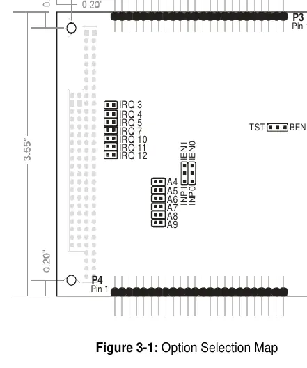
- Figure 3-1: Illustrates the location of jumpers for IRQ selection, base address (A4-A9), and buffer control (TST/BEN).
Model compatibility
- Compatible with industry standard I/O racks like Gordos, Opto-22, Potter & Brumfield.
- Designed for 16-bit or 8-bit PC/104 bus sockets.

Manual page author
Emily Carter
User documentation editor
Prepares concise manual descriptions and highlights the most useful setup, operation, and maintenance information for readers.