Industrial / I/O Modules
User Manual for ELPRO 115S-XX Serial Expansion Modules
Comprehensive user manual for ELPRO 115S-XX series expansion modules. Includes installation, wiring diagrams, configuration settings, Modbus address maps, and troubleshooting for 115S-11, 115S-12, and 115S-13 models.
Table of contents
Manual images
Click an image to enlargeQuick guide from the manual
The ELPRO 115S-XX series are serial expansion I/O modules designed for industrial environments. Before installation, ensure the power supply is 10.8-30 VDC and the equipment is properly grounded. Configuration is performed using the ELPRO E-Series software or the dedicated 115S configuration utility (cfg_115S_Vx.xx.exe). For initial configuration, set the address switches to 00 and connect via the RS232 port.
Overview
The 115S modules provide I/O expansion for ELPRO Legacy (105U, 905U) and Condor Range products. They support Modbus RTU/ASCII and the older Elpro Legacy protocol. Models include:
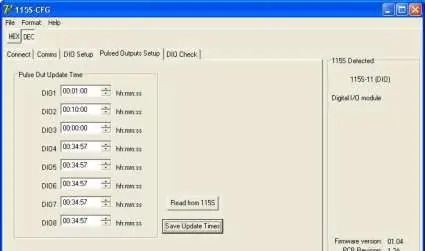
- 115S-11: Digital I/O and Pulse I/O.
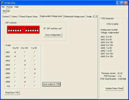
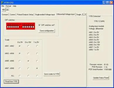
- 115S-12: Digital I/O and Analog Inputs.
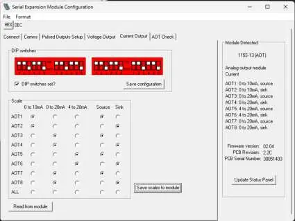
- 115S-13: Digital I/O and Analog Outputs.
Installation
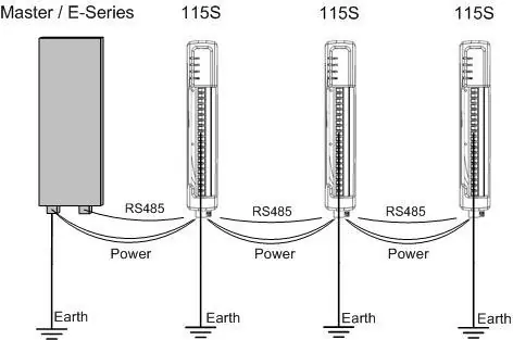
Modules can be connected in a multi-drop RS485 configuration. Ensure the last module in the chain has the RS485 termination switch set to 'terminate'. Power is supplied to the 4-way connector. Address switches on the bottom panel must be set to 01-99 for Modbus operation or 00 for Legacy protocol. Always reset the module after changing address switches.
Configuration
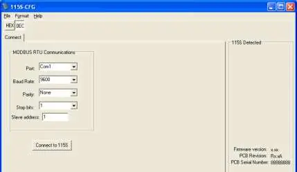
Hardware settings, such as pulse rates and analog scales, are adjusted via the configuration software. Connect the module to a PC COM port using a straight-through DB9 cable. In the software, select the appropriate module type and configure communication parameters (default: 9600 baud, None parity, 1 stop bit). For analog modules, ensure DIP switches under the access panel are set correctly before applying software configurations.
Signal Connections
All connections must be SELV only. Digital inputs are activated by connecting to EARTH via voltage-free contacts or NPN-transistor switches. Digital outputs are open-collector transistor switches to EARTH (max 30VDC, 200mA). Analog inputs on the 115S-12 support grounded single-ended or floating differential modes. Analog outputs on the 115S-13 support voltage or current (source/sink) modes.
Operation
The operation of I/O can be verified using the 'Check' tabs in the configuration software. Digital inputs are reflected in the software status, and digital outputs can be toggled for testing. Analog values are represented as 16-bit integers (hex 4000 for 0%, hex C000 for 100%).
Specifications
Operating temperature range is -40 to +60°C (up to +70°C for 115S-11 in non-hazardous locations). Power supply is 10.8-30 VDC. Digital inputs require <2.1VDC for on-state. Analog inputs/outputs feature 16-bit/12-bit resolution respectively.
Official resources from the manual
Practical help
Common problems
Cannot communicate with the module
Check the RS232 cable connection, ensure the COM port is correct, and verify the address switches are set to 00 for configuration mode.
Outputs resetting unexpectedly
Check the 'Modbus Output Timeout' setting. Ensure the timeout value is greater than the Modbus Master poll time.
Analog input/output readings are incorrect
Verify that the physical DIP switch settings on the module match the configuration selected in the software.
Before use
- Verify power supply is 10.8-30 VDC.
- Ensure all equipment is properly grounded.
- Set address switches to 00 for initial configuration.
- Install the appropriate configuration software (E-Series or cfg_115S_Vx.xx.exe).
- Check wiring diagrams for your specific model (115S-11, 115S-12, or 115S-13).
Specs in practice
- 16-bit register
- Data format used for analog values and pulse counts.
Images and diagrams
- Figure 2-1: Overview of module parts, connectors, and LEDs.
- Figure 2-2: Power and RS485 terminal wiring.
- Figure 2-5/2-6: Digital input and output connection diagrams.
- Figure 2-7/2-8/2-9/2-10: Analog input wiring configurations.
- Figure 2-11/2-12/2-13: Analog output wiring configurations.
Model compatibility
- 115S-11: Digital I/O and Pulse I/O.
- 115S-12: Digital I/O and Analog Inputs.
- 115S-13: Digital I/O and Analog Outputs.
- Compatible with ELPRO Legacy (105U/905U) and Condor Range radios.

Manual page author
Emily Carter
User documentation editor
Prepares concise manual descriptions and highlights the most useful setup, operation, and maintenance information for readers.