Electronics / Security Cameras
Installation Guide for Avigilon H6A and H6X Bullet Camera
Comprehensive installation and setup guide for Avigilon H6A and H6X series bullet cameras. Includes mounting instructions, wiring diagrams, configuration steps, and troubleshooting.
Quick answers from the manual
Quick answer
- This guide provides installation, wiring, and configuration instructions for Avigilon H6A and H6X bullet cameras, including mounting, power failover, and troubleshooting. p. 1, 6, 8, 20
Key actions
- Mounting the camera p. 8, 13, 15, 16
- Initializing the camera p. 15, 22
- Resetting to factory defaults p. 25, 32
First start
- Connect the camera to the network/power, access the web interface or ACC software, and create an administrator user. p. 15, 16, 22
Problems and fixes
Green LED off, amber on
Perform a factory reset using the physical firmware revert button.
p. 23, 30
Both LEDs off
Check power and network cable; ensure LEDs are not disabled in the web interface.
p. 23, 30Maintenance and reset
- Use the firmware revert button in the configuration panel for 3 seconds. p. 25, 32
Technical specifications
| Parameter | Value | Meaning | Pages |
|---|---|---|---|
| Power Input | 12-24 VDC or PoE | Power supply requirements. | p. 4, 20, 27 |
Where to find it in the PDF
- Installation p. 6, 8, 15, 16
- Troubleshooting p. 23, 30, 31
Table of contents
Manual images
Click an image to enlargeQuick guide from the manual
This guide provides instructions for installing and configuring Avigilon H6A and H6X bullet cameras. Key steps include mounting the junction box, connecting power and network cables, and initializing the camera via the web interface or Avigilon Control Center (ACC). Note that H6A models include a built-in microphone, while H6X models do not.
Installation
Before installing, ensure you have the necessary tools, including the provided T20 Pin-In star-shaped driver. The camera should be mounted to a stable surface, ideally above 2.74 m (9 feet), with a downward tilt of no more than 45 degrees.
Mounting the Junction Box
- Use the provided mounting template to drill holes in the mounting surface.
- If using a side conduit, secure the conduit pipe with a clamp.
- Fasten the junction box to the surface and pull cables through.
- It is recommended to apply silicone sealant around the edge of the junction box to prevent moisture ingress.
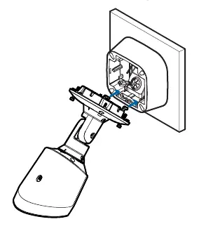
- Hook the camera onto the junction box using the mounting hooks to hold it in place while connecting cables.
Connecting Cables
Ensure cable connections are protected from moisture. Connect external I/O devices or microphones to the terminal blocks if required. Thread the Ethernet cable through the grommet and connect it to the RJ-45 port. The Link LED will turn on once a network link is established.
Configuration
Once installed, you must initialize the camera by creating an administrator user. This can be done via the camera's web interface, the Camera Configuration Tool, or the ACC Client software. If the camera is in a factory default state, you will be prompted to create a user upon first connection.
Power and External Devices
The camera supports Power over Ethernet (PoE) or external 12-24 VDC power. H6X models support seamless failover between PoE and auxiliary power, provided PoE Class 4 (25.5W) is available. H6A models experience a non-seamless failover, meaning they may power off briefly when switching power sources.
Troubleshooting
If the camera is not functioning as expected, check the Connection Status LED indicator. If the green LED is off and the amber LED is on, or if both LEDs are off, perform a physical factory reset using the firmware revert button located in the configuration panel. Press and hold the button for 3 seconds using a paperclip.
Practical help
Common problems
Camera not connecting or streaming
Ensure the camera is receiving power and using a functional network cable. Check the General setup page in the web interface to ensure LEDs are not disabled.
Insufficient power message
Ensure the camera is connected to a PoE Class 4 (25.5W) source if seamless failover is required.
LEDs indicate error or no connection
Perform a physical factory reset using the firmware revert button in the configuration panel.
Before use
- Verify mounting surface is stable and suitable for installation.
- Ensure PoE Class 3 or 4 power or 12-24 VDC external power is available.
- Have a T20 Pin-In star-shaped driver ready for installation and configuration panel access.
- If using a microSD card, ensure it is Class 10 or better.
- Create an administrator user before the camera is operational.
Images and diagrams
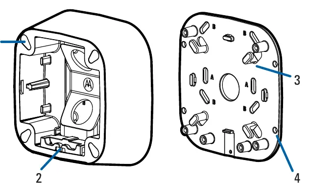
- Junction box: Contains mounting holes, cable hooks for excess cable, and a mounting hinge.
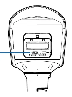
- Configuration panel: Contains microSD slots, USB-C port, connection status LEDs, and the firmware revert button.
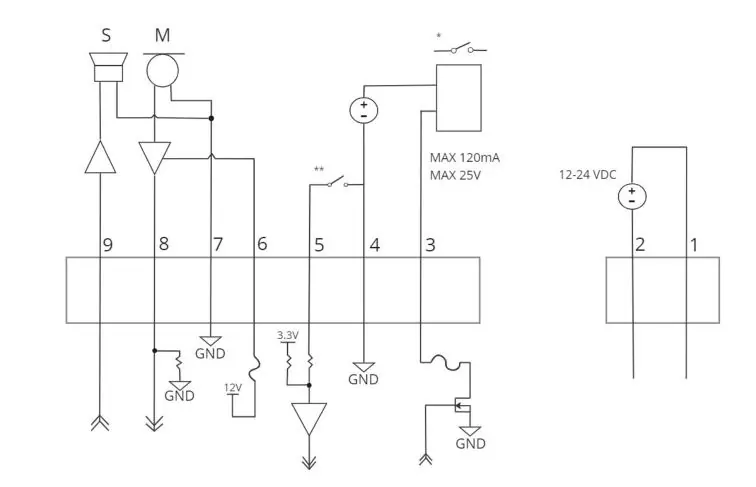
- Wiring diagram: Shows pinout for I/O terminal block, including power, digital I/O, and audio connections.
Model compatibility
- Microphone is not available on H6X camera models.
- Seamless failover is only guaranteed with PoE Class 4 (25.5W) power.
- The camera must not be powered with 24 VAC auxiliary power.

Manual page author
Michael Turner
Technical manual editor
Reviews PDF manuals for structure, safety notes, and practical product details so readers can find the right information quickly.