Electronics / Security Cameras
Installation Guide for Avigilon H5SL Bullet Camera
A comprehensive installation and setup guide for the Avigilon H5SL Bullet Camera. This manual covers mounting procedures, wiring diagrams, initial configuration, network setup, and troubleshooting for LED status indicators.
Table of contents
Manual images
Click an image to enlargeQuick guide from the manual
This document provides essential installation and operation information for the Avigilon H5SL Bullet Camera. The device must be powered by a Power over Ethernet (PoE) source rated at 48 VDC, 9W minimum. Installation should be performed by qualified personnel only. Do not connect the device directly to mains power.
Overview
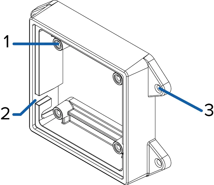
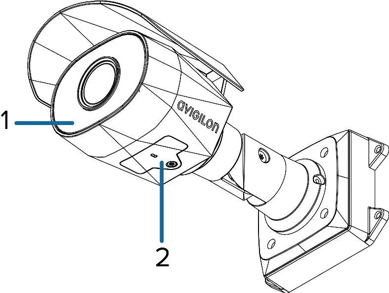
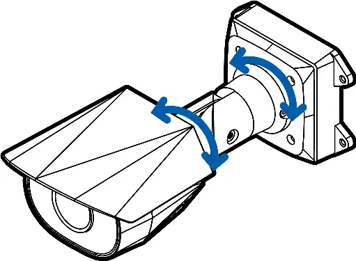
The camera features a mounting bracket with integrated hook slots for easy installation. The configuration panel, located under a cover, provides access to the microSD card slot, micro USB port for Wi-Fi adapters, and status LEDs. The camera body includes an adjustable sun shroud and mount arm for precise positioning.
Installation
Before installing, ensure the mounting surface can support the camera. If cables are not routed through the mounting surface, use the optional junction box (H4-BO-JBOX).
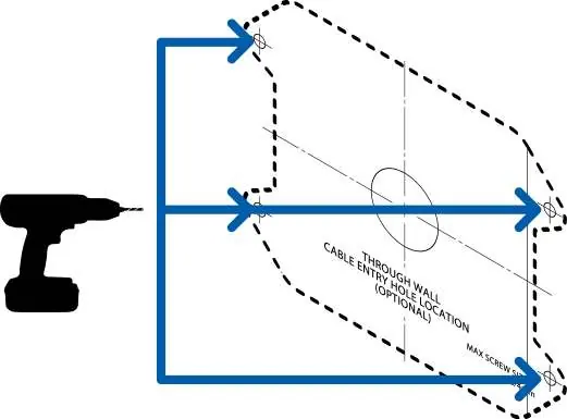
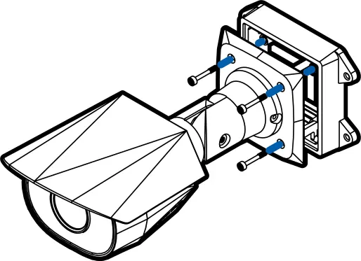
- Use the provided mounting template to drill four mounting holes and a cable entry hole.
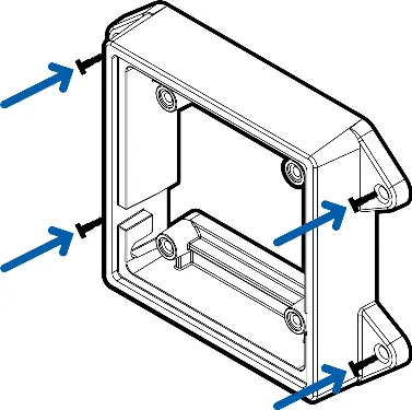
- Fasten the mounting bracket to the surface. Applying silicone sealant around the edge is recommended to prevent moisture ingress.
- Insert the camera's mounting hooks into the bracket slots to hang the camera while connecting cables.
- Connect external audio/IO devices if required.
- Install the protective cable boot over the Ethernet connection to protect against dust and moisture.
- Connect the network cable to the Ethernet port.
- Raise the camera to cover the bracket and fasten it using the camera mounting screws.
Configuration
Cameras manufactured after January 1, 2020, do not have a default username or password. You must create an administrator user before the camera is operational. Configuration can be performed via the camera's web interface, the Avigilon Camera Configuration Tool, the Avigilon Control Center software, or the mobile web interface using a USB Wi-Fi adapter.
Troubleshooting
If the camera is not functioning as expected, check the connection status LED indicators. If the green LED is off and the amber LED is on, or if both LEDs are off, perform a factory reset using the physical firmware revert button located in the configuration panel. Hold the button for three seconds while the device is powered on.
Practical help
Common problems
Green LED is off and amber is on
Perform a factory reset using the physical firmware revert button.
Both LEDs are off and no video stream
Check that the camera is receiving power and using a functional network cable. Ensure LEDs are not disabled in the web interface.
Cannot log in to the camera
For cameras manufactured after Jan 1, 2020, you must create an administrator user first. There is no default username/password.
Before use
- Verify PoE power source (48 VDC, 9W min) is available.
- Ensure mounting surface is suitable for the camera weight.
- Have a T20 Pin-In star-shaped driver for the configuration panel cover.
- Prepare silicone sealant for the mounting bracket edge.
- Ensure a microSD card (Class 10 or better) is available if onboard storage is needed.
Images and diagrams
- Mounting bracket: Shows camera mounts, hook slots, and mounting holes.
- Wiring diagram: Details pinout for audio/IO cables (Grey: Audio In, Pink: Audio Out, Yellow: Digital Input, Brown: Digital Output).
Model compatibility
- Compatible with Avigilon Control Center and 3rd party VMS.
- Requires PoE (Limited Power Source, 48 VDC, 9W min).

Manual page author
Emily Carter
User documentation editor
Prepares concise manual descriptions and highlights the most useful setup, operation, and maintenance information for readers.