Electronics / Security Cameras
Installation Guide for Avigilon H5A Box Camera
A comprehensive installation and setup guide for the Avigilon H5A Box Camera. Includes mounting instructions, cable connections, power requirements, initial configuration, and troubleshooting steps.
Quick answers from the manual
Quick answer
- The Avigilon H5A Box Camera requires a qualified installer. It supports PoE or external power (12V DC/24V AC). Initial setup requires creating an administrator user via the web interface or configuration tool. p. 3, 4, 11
Key actions
- Mounting the camera p. 3, 8
- Performing a factory reset p. 13, 20
First start
- Create an administrator user via web interface or configuration tool. p. 4, 11
Problems and fixes
LEDs off or unresponsive
Check power and network cable. Perform physical factory reset using the revert button.
p. 11, 18Maintenance and reset
- Use the firmware revert button on the rear of the camera. p. 13, 20
Technical specifications
| Parameter | Value | Meaning | Pages |
|---|---|---|---|
| Power | PoE (48V DC) or 12V DC/24V AC | Power requirements | p. 3, 15 |
| Mounting | 1/4"-20 UNC | Thread size | p. 8, 10 |
Where to find it in the PDF
- Overview and Ports p. 1, 2, 8, 9
- Installation and Wiring p. 3, 10, 15, 16
- Configuration p. 4, 5, 6, 7
- Troubleshooting p. 11, 13, 14
Table of contents
Manual images
Click an image to enlargeQuick guide from the manual
This guide provides essential installation and configuration steps for the Avigilon H5A Box Camera. Before starting, ensure you have the necessary tools, including a small slotted screwdriver (2 mm blade) and a suitable mounting bracket or tripod. The camera requires either Power over Ethernet (PoE) or an external 12V DC/24V AC power source.
Safety Information
Installation must be performed by qualified personnel only. Adhere to the following safety precautions:
- Do not use near water or expose to rain/moisture.
- For indoor use only.
- Do not connect directly to mains power.
- Use only UL-listed mounting brackets capable of supporting at least 0.7 kg (1.6 lb).
- Do not open or disassemble the device; there are no user-serviceable parts.
Installation
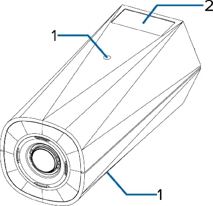
Mounting the Camera
The camera features mounting points on both the top and bottom of the body. These points accept 1/4"-20 UNC threaded bolts, compatible with standard tripods and mounting brackets.
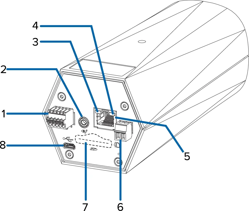
Connecting Cables
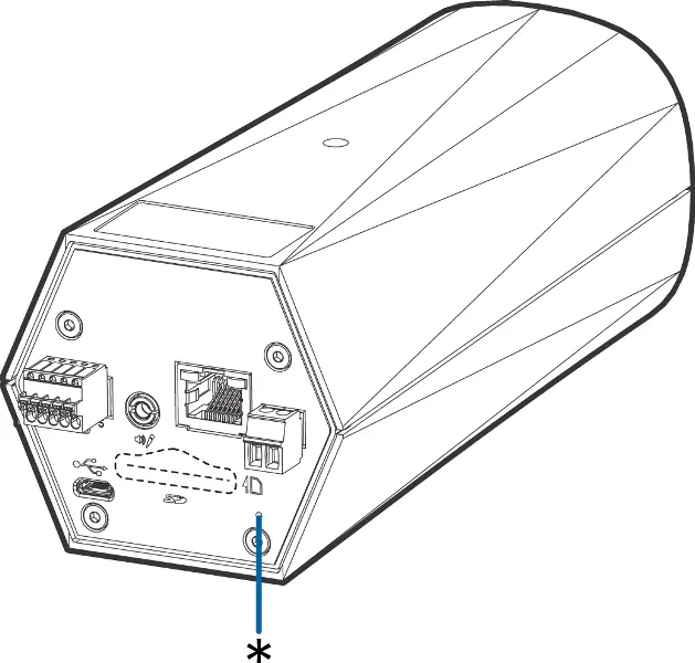
Refer to the rear view of the camera to locate the I/O connector block, audio/video connector, Ethernet port, and power connector. If PoE is not available, connect an external 12V DC or 24V AC power source to the power connector block. Ensure wires are stripped to 1/4" (6 mm) before insertion.
Initial Configuration
Cameras manufactured after January 1, 2020, do not have a default username or password. You must create an administrator user before the camera is operational. This can be done via:
- The camera's web interface (access via IP address).
- Avigilon Camera Configuration Tool.
- Avigilon Control Center software.
- USB Wi-Fi Adapter.
Once configured, you can access the live video stream through the web interface or management software.
Troubleshooting
If the camera is not functioning as expected, check the LED indicators. If the camera is unresponsive, perform a factory reset by pressing and holding the physical firmware revert button on the rear of the camera for three seconds.
Practical help
Common problems
Camera not powering on
Verify that the PoE connection is active or that the external 12V DC/24V AC power source is correctly wired to the power connector block.
Cannot access camera web interface
Ensure you have created an administrator user. If the camera is in factory default state, use the Avigilon Camera Configuration Tool to discover and initialize it.
LEDs are off
Check that the camera is receiving power and that the network cable is functional. If issues persist, perform a physical factory reset.
Before use
- Verify power source (PoE or external 12V DC/24V AC)
- Ensure mounting surface supports at least 0.7 kg
- Have a small slotted screwdriver (2 mm blade) ready
- Ensure network connectivity is available
- If using SD storage, ensure card is 8GB+ and Class 10 or better
Specs in practice
- External Power
- 12 VDC or 24 VAC, 7-8 W min
- Mounting Thread
- 1/4"-20 UNC standard photographic thread
Images and diagrams
- Rear view shows the layout of the I/O block, audio/video connector, Ethernet port, power connector, SD card slot, and USB port.
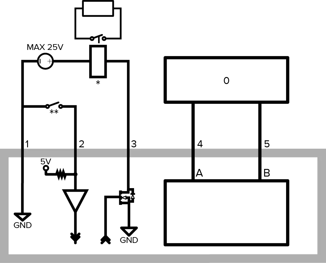
- Wiring diagram for the I/O connector block details the pinout for relay input/output and RS-485 connections.
Model compatibility
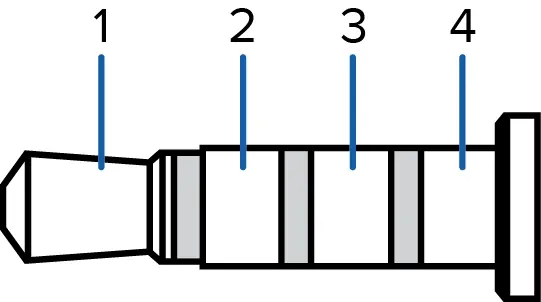
- Only 2.0 megapixel models support external video monitor connection via the A/V connector.
- The camera supports line-level mono audio input and NTSC/PAL video output.

Manual page author
David Miller
Documentation analyst
Organizes user manual content into clear summaries, with attention to model details, product context, and everyday usability.