Automotive / Car Audio
Installation Guide for Axxess AXTC-FD3 Steering Wheel Control and Data Interface
A comprehensive installation and programming guide for the Axxess AXTC-FD3 interface. This manual covers wiring connections, steering wheel control programming, LED troubleshooting, and advanced settings for Ford vehicles.
Quick answers from the manual
Quick answer
- The AXTC-FD3 is a steering wheel control and data interface for Ford vehicles. Installation involves connecting the harness, programming via the steering wheel buttons, and verifying the LED status. p. 1, 3
Key actions
- Programming the interface p. 3
- Resetting the interface p. 4
First start
- Initial setup p. 3
Problems and fixes
LED shows Solid Red
Programming failed. Reset the interface and try again.
p. 4, 9Maintenance and reset
- Resetting the interface p. 4
Technical specifications
| Parameter | Value | Meaning | Pages |
|---|---|---|---|
| Accessory Power | 10-amp | Power output provided by the interface. | p. 1 |
Where to find it in the PDF
- Installation Instructions p. 1
- Wiring Connections p. 2
- Programming p. 3
- Troubleshooting p. 4
Table of contents
Manual images
Click an image to enlargeQuick guide from the manual
The Axxess AXTC-FD3 is designed for non-amplified Ford vehicles to retain steering wheel controls and provide accessory power. Important: The interface does not retain SYNC. Before installation, disconnect the negative battery terminal. The programming process requires the driver's door to be open and the ignition to be cycled.
Interface features
- Provides 10-amp accessory power.
- Retains steering wheel audio controls.
- Auto-detects vehicle type and radio connection.
- Non-volatile memory retains settings after battery disconnection.
- Micro-B USB updatable.
Installation and wiring
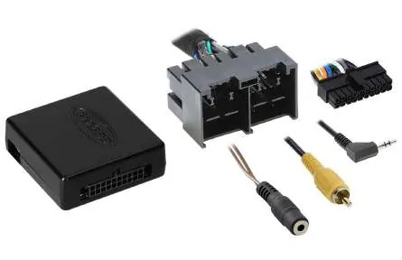
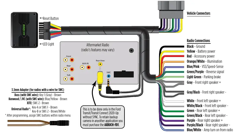
Connect the AXTC-FD3 harness to the interface and the vehicle's wiring harness. Refer to the wiring diagram for specific color-coded connections, including ground, battery power, accessory power, illumination, and speaker outputs. For radios with a 3.5mm SWC input, use the provided adapter and connect the appropriate wire (Brown or Brown/White) based on the radio brand.
Programming
- Open the driver's door and keep it open.
- Cycle the ignition to ON and wait 5 seconds.
- Connect the harness to the interface and the vehicle.
- Locate the Volume Up button on the steering wheel. Tap it at a heartbeat pace until the LED stops flashing.
- The LED will flash Green & Red while programming the radio, then Green & Red while programming the vehicle.
- Once the LED turns solid Green, cycle the ignition OFF, then back ON.
- Test all functions.
Troubleshooting
If the interface fails to function, press the reset button and repeat the programming process. The LED status indicates the programming state:
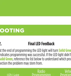
- Solid Green: Programming successful (Pass/Pass).
- Slow Red Flash: Radio programming failed.
- Slow Green Flash: Vehicle programming failed.
- Solid Red: Both sections failed.
If steering wheel controls do not work despite a solid Green LED, verify the 3.5mm jack is securely plugged into the correct input on the radio.
Advanced features
The interface supports changing the radio type and dual assignment of steering wheel buttons. These can be configured using the Axxess Updater app or by following the specific button-press sequences outlined in the manual. Note that Apple mobile devices may require the AX-HUB for these features.
Practical help
Common problems
Interface fails to function
Press and release the reset button, then repeat the programming process from step 4.
Steering wheel controls do not work
Ensure the 3.5mm jack is plugged into the correct SWC input on the radio, not the Bluetooth Mic or AUX input.
Wrong radio detected
Reference the Radio LED Feedback table and use the 'Changing Radio Type' procedure to manually select the correct radio.
Before use
- Disconnect the negative battery terminal.
- Verify the vehicle is a non-amplified model.
- Ensure the radio is compatible with the interface.
- Have crimping tools, solder, or heat shrink ready.
- Keep the driver's door open during programming.
Specs in practice
- Accessory Power
- Provides 10-amp power output for the aftermarket radio.
- Non-volatile memory
- Retains settings even after battery disconnection or interface removal.
Images and diagrams
- Wiring diagram illustrates connections for vehicle and radio harnesses.
- LED feedback table helps diagnose programming success or failure.
Model compatibility
- Designed for non-amplified Ford models only.
- Does not retain SYNC.
- Requires AXBUCH-FD1 for backup camera retention in some applications.

Manual page author
Emily Carter
User documentation editor
Prepares concise manual descriptions and highlights the most useful setup, operation, and maintenance information for readers.