Industrial / Access Control
User Manual for Uniview 0235C4SJ Face Recognition Access Control Terminal
Quick guide for the Uniview 0235C4SJ Face Recognition Access Control Terminal. Includes installation, wiring, web login, and face recognition setup instructions.
Table of contents
Manual images
Click an image to enlargeQuick guide from the manual
This document provides essential instructions for installing and configuring the Uniview 0235C4SJ Face Recognition Access Control Terminal. It covers physical installation, wiring, initial startup, web interface login, and best practices for face recognition accuracy.
Packing List
Ensure your package contains the following items:
- Face recognition access control terminal
- Screw component (3 sets)
- Installation sticker
- Power adapter
- Power cable
Device Structure
The device features a display screen, camera, light supplement lamp, microphone, loudspeaker, and various interfaces including a 16-pin interface and network port. Note that certain models may have different camera configurations.
Installation
Installation Environment: Avoid intense direct light and backlighting. Ensure the ambient light is bright.
Tools Required: Phillips screwdriver, antistatic gloves/wrist strap, drill, tape measure, marker, silicone rubber, and silicone gun.
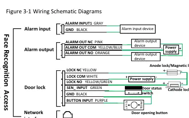
Device Wiring: Plan the layout for power, network, door lock, and alarm cables before installation. The wiring diagram details connections for alarm input/output devices, door locks (anode/cathode/magnetic), and door opening buttons.
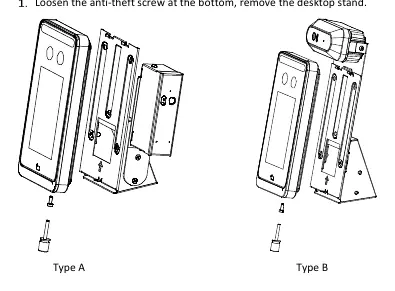
Mounting: The device supports desktop mount and standing pole mount (pole purchased separately). For pole mounting, remove the desktop stand, secure the device to the pole, route cables through the pole, and connect them to the terminal.
Device Startup
After installation, connect the power adapter to the mains and the device. The display screen will light up and show the live view upon successful startup.
Web Login
To manage the device via a PC:
- Open Internet Explorer (IE9 or later).
- Enter the device IP address (default: 192.168.1.13).
- Log in with the default username (admin) and password (123456).
- Important: Change the default password immediately to a strong password (at least nine characters, including digits, letters, and special characters).
Personnel Management
Personnel can be managed via the Web interface or the device GUI:
- Web Interface: Navigate to Setup > Intelligent > Face Library to add, modify, or delete personnel.
- GUI: Tap and hold the main interface for 3 seconds, enter the activation password, and select User Management.
Face Recognition Best Practices
To ensure accurate recognition:
- Photo Requirements: Use bareheaded, full-face photos with a pure background (white/blue). Avoid heavy makeup.
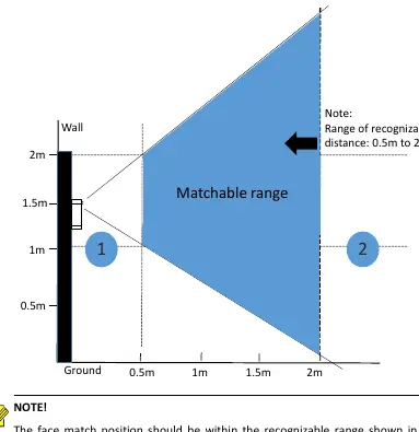
- Positioning: The recognizable distance is 0.5m to 2m. If recognition fails, adjust your distance accordingly.
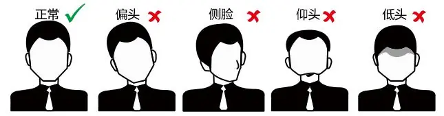
- Posture: Keep a natural expression, face the recognition window directly, and avoid tilting your head or looking away.
Safety and Security
Always keep firmware updated, disable unused features like UPnP or SNMP, and use strong passwords. The device must be installed and serviced by trained professionals. Ensure proper ventilation and do not cover device vents.
Manufacturer information
Uniview
Practical help
Common problems
Face match fails in area 1 (too close)
Move backward to increase distance.
Face match fails in area 2 (too far)
Move forward to decrease distance.
Cannot access web interface
Ensure you are using the correct IP (default 192.168.1.13) and default credentials (admin/123456).
Cables disconnected during installation
Do not pull cables; ensure they are routed carefully through the pole.
Before use
- Avoid installing in areas with intense direct light or backlighting.
- Ensure you have a Phillips screwdriver, drill, and silicone sealant.
- Plan cable routing for power, network, and door locks.
- Verify the power supply provides stable voltage.
- Ensure the standing pole (if used) is purchased separately.
Specs in practice
- Recognizable distance
- 0.5m to 2m
- Default IP Address
- 192.168.1.13
- Default Username
- admin
- Default Password
- 123456
Images and diagrams
- Wiring diagram: Shows connections for alarm input/output, door locks, and network interface.
- Installation diagrams: Illustrate the steps for desktop and standing pole mounting.
- Face match position diagram: Defines the optimal 0.5m-2m range for recognition.
- Posture diagram: Shows correct vs. incorrect head positions for recognition.
Model compatibility
- Standing pole is not included in the delivery.
- Certain models may have different camera configurations.
- Requires IE9 or later for web interface access.

Manual page author
Michael Turner
Technical manual editor
Reviews PDF manuals for structure, safety notes, and practical product details so readers can find the right information quickly.