Electronics / Monitors
User Guide for Uniview 0235C8YQ Access Control Terminal
Quick guide for the Uniview 0235C8YQ access control terminal. Learn about installation, wiring, web configuration, and optimal recognition settings.
Table of contents
Manual images
Jump to the sectionQuick guide from the manual
This document provides essential instructions for installing and configuring the Uniview 0235C8YQ Intelligent Recognition Access Control Terminal. Key procedures include physical installation, wiring, and initial network setup. Users should ensure the device is installed by a trained professional and that all safety and network security guidelines are followed.
Packing List
Ensure the following items are included in the package. Contact your dealer if any items are missing or damaged:
- Intelligent recognition access control terminal
- Screw components (2 sets)
- Wall mount bracket
- T10 screwdriver
- Drill template
- Tail cable
- Cover
- Product documents
Device Installation
Follow these steps to mount the device securely:
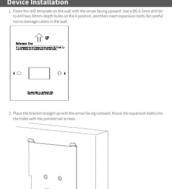
- Prepare the wall: Paste the drill template on the wall with the arrow facing upward. Use a 6-6.5mm drill bit to drill two 30mm-depth holes at the marked positions. Insert expansion bolts, taking care not to damage cables inside the wall.
- Mount the bracket: Place the bracket with the arrow facing outward. Secure it using the expansion bolts and pointed tail screws.
- Connect cables: Connect the network cable to the rear panel interface. Connect the integrated cables to the door sensor, alarm, and other devices as required.
- Attach cover: Fasten the cover to the terminal using three short Phillips screws.
- Secure terminal: Loosen the tamper-proof screws on both sides of the device using the T10 screwdriver. Align the hook on the bracket with the groove on the terminal, secure the terminal to the bracket, and tighten the tamper-proof screws.
Wiring
The device uses a tail cable with color-coded wires for various functions:
- Power: Red (12V power input), Black (GND).
- Door/Button: Light green (Door magnetic input), Yellow/Black (Button input), Pink (Door lock_NC), White/Yellow (Door lock_COM), White/Green (Door lock_NO).
- Communication: Orange (RS485_A), Yellow (RS485_B), Blue (Wiegand input_D0), White (Wiegand input_D1), Brown (Wiegand output_D0), Green (Wiegand output_D1).
- Alarm: Purple (Alarm input_1), White/Purple (Alarm input_2), Gray (Alarm output_NC), White/Orange (Alarm output_COM), White/Blue (Alarm output_NO).
Startup and Web Login
After installation, connect the power adapter to the device and the mains supply. To configure the device via a web browser:
- Default IP Address: 192.168.1.13
- Default Username: admin
- Default Password: 123456
Note: For security, change the default password immediately upon first login. Use a strong password containing at least nine characters, including uppercase and lowercase letters, digits, and special characters.
Recognition Requirements
To ensure accurate recognition, follow these guidelines:
- Photo Collection: Face the camera directly without wearing hats or caps. Ensure the photo shows both ears and the area from the top of the head to the bottom of the neck. Use true color photos with solid backgrounds (white or blue). Avoid heavy makeup.
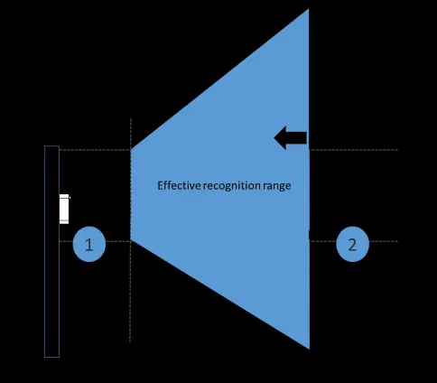
- Position: The effective recognition distance is 0.5m to 2m. Avoid standing in restricted areas 1 or 2 as indicated in the manual.
- Posture: Maintain a natural expression. Avoid tilting, turning to the side, raising, or bowing the head.
Safety and Security
Ensure the device is installed in a proper environment with adequate ventilation. Do not stack devices. Use a UL-certified power supply. For network security, regularly change passwords, enable HTTPS/SSL, disable unused ports (like UPnP and SNMP), and isolate the video surveillance network.
Manufacturer information
Uniview
Practical help
Common problems
Device fails to recognize user
Ensure the user is within the 0.5m-2m range, facing the camera directly, and not wearing a hat or heavy makeup.
Cannot access web interface
Verify the device is connected to the network and try accessing the default IP 192.168.1.13.
Tamper alarm triggered or device loose
Ensure the tamper-proof screws on both sides of the device are tightened correctly after mounting.
Before use
- Verify all items from the packing list are present.
- Ensure the wall surface is flat and suitable for mounting.
- Check for existing cables inside the wall before drilling.
- Prepare a user-supplied network cable and power adapter.
- Ensure the power supply meets the device's voltage requirements.
Specs in practice
- Recognition Distance
- The optimal range for the camera to identify a user is between 0.5m and 2m.
- Default Credentials
- The initial login is username 'admin' and password '123456'.
Images and diagrams
- The drill template helps mark the exact positions for the two mounting holes.
- The recognition range diagram illustrates the effective area (0.5m-2m) where the user should stand.
- The posture guide shows correct head alignment (facing forward) versus incorrect poses like tilting or bowing.
Model compatibility
- Requires a UL certified power supply that meets LPS requirements.
- Supports standard Wiegand input/output protocols for access control integration.

Manual page author
Emily Carter
User documentation editor
Prepares concise manual descriptions and highlights the most useful setup, operation, and maintenance information for readers.