Electronics / Cameras
User Guide for Uniview 0235CBQK Swing Speed Gate
A comprehensive installation and operation guide for the Uniview 0235CBQK Swing Speed Gate. This manual covers site preparation, barrier installation, wiring diagrams, network configuration, and remote control pairing.
Table of contents
Manual images
Jump to the sectionQuick guide from the manual
This document provides essential instructions for the installation, wiring, and configuration of the Uniview 0235CBQK Swing Speed Gate. The device must be installed and maintained by a trained professional. Ensure power is completely disconnected during all installation and maintenance procedures to prevent injury or equipment damage.
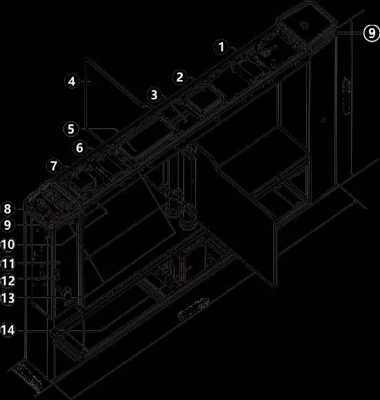
Device Installation
Before beginning, ensure the site is prepared according to the lane width of your specific device. The installation requires drawing parallel lines and creating slots for cabling.
Installation Preparation
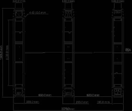
- Draw two parallel lines along the length of the gate, spaced 1870 mm apart.
- Create slots at the bottom of the gate for embedding bridging and network cables. Recommended slot depth is 90–120 mm.
- Use PVC conduit pipes for cable routing.
Install Barriers
- Remove screws securing the clamps to the posts.
- If using acrylic barriers, attach rubber grommets to the clamps.
- Align the barrier with the post, ensuring the perforated side is against the post.
- Secure the barrier using the provided clamps and screws.
Secure the Gate
- Drill holes at designated locations and install expansion anchors.
- Unlock the bottom maintenance lock to access mounting holes.
- Align the pedestal, insert expansion bolts, and hammer them in to secure the gate to the floor.
Wiring
Wiring must be completed for each speed gate unit. Ensure all connection points are properly insulated.
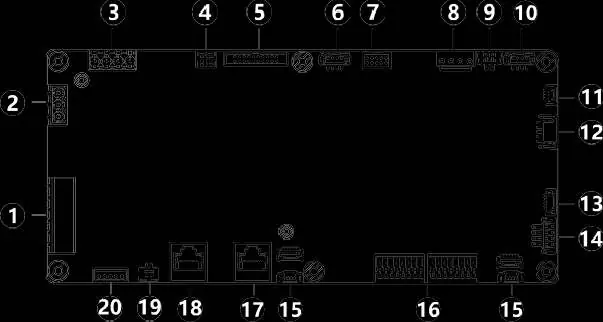
Control Board Wiring
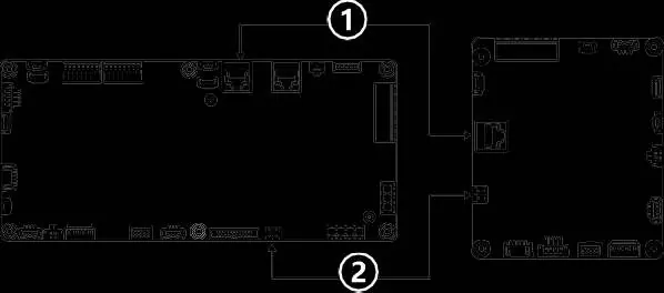
- Use bridging cables to connect the main control board of the right pedestal to the sub control board of the middle pedestal, and the middle to the left.
- Use white control board bridging network cables to connect the boards in the same sequence.
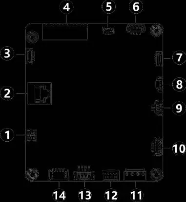
Access Control Board Wiring
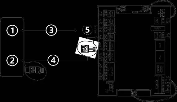
- Use black access control board bridging network cables to connect the main and sub access control boards across the pedestals.
- Connect external devices (e.g., push buttons, smoke detectors) to the CASE IN1/CASE IN2 interfaces.
- Connect verification terminals using the provided adapter and extension cables.
Circuit Breaker Wiring
- Ensure input voltage is stable (AC 110V or 220V at 50Hz).
- Connect L to L and N to N; do not reverse connections.
- Ensure all bare wire ends are insulated.
Startup and Configuration
After installation, power on the gate and toggle the circuit breaker. The barriers should open and close once, the access indicator will turn green, and the buzzer will sound.
Web Login
Access the device via a web browser using the following default settings:
- Default IP address: 192.168.1.13
- Default username/password: admin / 123456
It is strongly recommended to change the default password immediately to a strong password containing at least nine characters, including digits, letters, and special characters.
Remote Control Operations
- Pairing: Press and hold the Learn button on the receiver until the indicator flashes once. Press and hold both buttons on the remote control simultaneously until the receiver indicator flashes 5 times.
- Restore Factory Defaults: Press and hold the Learn button on the receiver until the indicator flashes rapidly twice. Note that this deletes all pairing information.
Manufacturer information
Uniview
Practical help
Common problems
Barrier does not move after power on
Check the circuit breaker connection and ensure the power supply provides stable 110V/220V AC.
Access indicator flashes red
This indicates an abnormal condition, such as unauthorized entry. Check system logs.
Remote control not functioning
Ensure the remote is paired with the receiver. If multiple receivers are in pairing mode, they may all pair simultaneously.
Before use
- Ensure installation is performed by a trained professional.
- Verify the floor is suitable for M12*100 expansion bolts (concrete).
- Check that all bridging cables and network cables are correctly routed.
- Ensure the power supply provides stable voltage (110V/220V AC).
- Confirm all wiring connections are insulated and secure.
Specs in practice
- 192.168.1.13
- Default IP address for web configuration.
- admin / 123456
- Default login credentials for the web interface.
Images and diagrams
- Control Board Wiring: Shows how to connect main and sub control boards using bridging cables.
- Barrier Installation: Illustrates the clamp and grommet assembly for acrylic barriers.
- Circuit Breaker: Details the connection of L, N, and PE wires.
Model compatibility
- Swing barriers must be purchased separately.
- Compatible with standard 110V or 220V AC power at 50Hz.

Manual page author
Michael Turner
Technical manual editor
Reviews PDF manuals for structure, safety notes, and practical product details so readers can find the right information quickly.