Industrial / Access Control
Uniview 0235C68W Face Recognition Access Control Terminal User Guide
Quick guide for the Uniview 0235C68W Face Recognition Access Control Terminal. Includes installation steps, wiring diagrams, web login credentials, and face recognition setup requirements.
Table of contents
Manual images
Click an image to enlargeQuick guide from the manual
This document provides essential instructions for installing and configuring the Uniview 0235C68W Face Recognition Access Control Terminal. It covers physical installation, wiring, initial startup, web interface access, and personnel management. Always ensure the device is installed by a trained professional.
Packing List
Ensure the package contains the following items. Contact your dealer if any are missing:
- Face recognition access control terminal
- Screw components (2 sets)
- Wall mount bracket
- T10 star-head key
- Drill template
- Tail cable
- Power cable
- Wiring terminal block
- Cover
- User manual
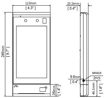
Product Overview
The terminal integrates face recognition technology and audio playing. It supports face authentication for door opening and people flow counting.
Installation
Installation Environment: Ensure adequate lighting at the site and avoid intense light sources.
Wiring: Plan wiring for power, network, door lock, Wiegand, alarm, and RS485 cables based on your networking conditions. Refer to the wiring schematic diagrams in the manual for specific pinouts (e.g., VDD12V, GND, ALM_IN, LOCK_NC/NO).
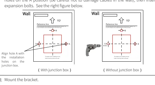
Installation Steps:
- Determine the position of the 86x86mm junction box.
- Paste the drill template. If using a junction box, align holes (A) with the box. If not, drill holes on the wall at position A.
- Mount the bracket by aligning it with the junction box holes and tightening the screws.
- Mount the cover using the provided screws.
- Use the T10 star wrench to unscrew the tamper-proof screws to access the card module.
- Fasten the terminal to the bracket hook.
- Tighten the tamper-proof screws to secure the device.
Startup
Connect the power adapter to the mains supply and the terminal's power interface. Upon first power-on, you are required to change the activation password. It is strongly recommended to set a strong password of at least nine characters, including digits, letters, and special characters.
Web Login
You can manage the terminal via a web browser. The default network settings are:
- IP Address: 192.168.1.13
- Subnet Mask: 255.255.255.0
- Gateway: 192.168.1.1
- Username: admin
- Password: 123456
Open Internet Explorer (IE9 or later), enter the IP address, and log in. Change the default password immediately for security.
Personnel Management
Personnel can be managed via the Web page, the terminal screen, or an entrance guard management platform. On the Web page, navigate to Setup > Intelligent > Face Library to add or modify personnel information.
Appendix
Face Photo Collection Requirements:
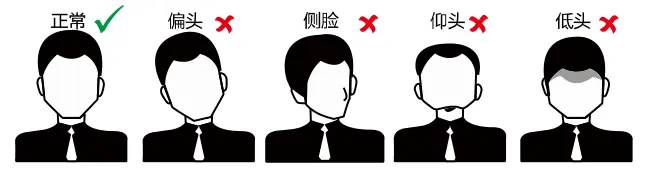
- Face the camera without hats or caps.
- Show both ears and the complete head-to-neck area.
- Use true color photos with a solid background (white or blue).
- Avoid heavy makeup.
- Ensure lighting is not too dark or too bright.
Recognition Range: The effective recognition distance is 0.5m to 2m. Keep your face centered in the recognition window and maintain a natural expression.
Safety Warnings
The device must be installed by a trained professional. Ensure proper ventilation, avoid stacking devices, and protect the device from liquids. Use a UL-certified power supply and ensure proper grounding.
Manufacturer information
Uniview
Practical help
Common problems
Face recognition fails
Ensure the person is within the 0.5m-2m range, the face is centered, and lighting is adequate (not too dark or bright).
Cannot log in to Web page
Verify the IP address (default 192.168.1.13) and ensure the device is on the same network as your computer.
Tamper alarm triggered
Ensure the tamper-proof screws are properly tightened using the T10 star wrench.
Before use
- Ensure adequate lighting at the installation site.
- Avoid intense light sources.
- Prepare tools: Phillips screwdriver, electric drill, tape measure, marker.
- Ensure the junction box is installed (if applicable).
- Change the default password upon first login.
- Ensure the power supply meets the device requirements.
Specs in practice
- Recognition distance
- 0.5m to 2m for optimal performance.
- Default Username
- admin
- Default Password
- 123456
Images and diagrams
- Wiring schematic shows connections for power, alarm, RS485, Wiegand, and door locks.
- Installation steps detail using a drill template and mounting the bracket.
- Face recognition range diagram illustrates the 0.5m-2m effective zone.
Model compatibility
- Supports connection to security modules.
- Compatible with IC cards and QR codes depending on the model.

Manual page author
David Miller
Documentation analyst
Organizes user manual content into clear summaries, with attention to model details, product context, and everyday usability.