Electronics / Headphones Earbuds
User Guide for Behringer DS2800 Distribution Splitter
Quick start guide for the Behringer DS2800 Professional 2-Input 8-Output Distribution Splitter. Learn how to connect, configure modes, set levels, and operate your device.
Quick answers from the manual
Quick answer
- The DS2800 is a professional 2-input, 8-output distribution splitter. It features two operation modes: 2-in/4-out and 1-in/8-out, selectable via the front panel switch. p. 1
Key actions
- Selecting Mode p. 7, 8, 9
- Adjusting Levels p. 7, 8, 9
First start
- Connect power, set levels to minimum, select mode, connect audio sources, power on, and adjust levels while playing audio. p. 10, 11
Problems and fixes
CLIP LED lights continuously
Rotate the channel's LEVEL knob counter-clockwise.
p. 7, 8, 9Technical specifications
| Parameter | Value | Meaning | Pages |
|---|---|---|---|
| Frequency response | 10 Hz to 75 kHz (±3 dB) | System frequency range | p. 11 |
| Max. input level | +21 dBu | Maximum signal level for inputs | p. 11 |
| Max. output level | +28 dBu | Maximum signal level for outputs | p. 11 |
Where to find it in the PDF
- Front Panel Controls p. 7
- Hook-up Diagrams p. 6
Table of contents
Manual images
Click an image to enlargeQuick Guide
The Behringer DS2800 is a professional 2-input, 8-output distribution splitter designed for audio distribution. It features two selectable operation modes: 2-in/4-out and 1-in/8-out. The unit is rack-mountable (1U) and provides balanced XLR connections for all inputs and outputs.
Hook-up and Modes
The DS2800 offers two primary operation modes, selectable via the front panel MODE switch:
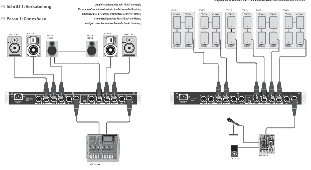
- 2-in/4-out mode (2-4): Activated when the MODE button is pressed inward (latched). In this mode, INPUT A feeds OUTPUTs 1-4, and INPUT B feeds OUTPUTs 5-8.
- 1-in/8-out mode (1-8): Activated when the MODE button is in the outward (unlatched) position. In this mode, only INPUT A is active, feeding all 8 outputs.
Connect your audio source devices to the INPUT A/B XLR jacks. Connect the OUTPUT and LINK jacks to your destination devices (e.g., amplifiers, active speakers, or other signal chain components).
Getting Started
- Connect the DS2800 to a power outlet using the included IEC power cable.
- Turn all LEVEL knobs on the front panel to the full counter-clockwise setting.
- Select the desired mode (2-in/4-out or 1-in/8-out) using the MODE switch.
- Connect your audio source devices to the INPUT A/B XLR jacks.
- Power on the unit by pressing the POWER button to the inward (ON) position.
- While playing audio, rotate each OUTPUT channel's LEVEL knob until you reach a satisfactory output level. Ensure the CLIP LED only lights occasionally. If the CLIP LED lights continuously, reduce the level by rotating the knob counter-clockwise.
Controls
The front panel provides the following controls:
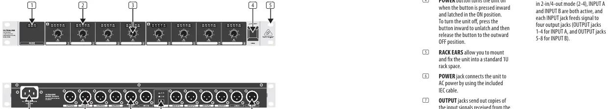
- MODE switch: Toggles between 2-in/4-out and 1-in/8-out modes.
- LEVEL knobs: Adjusts the output level for each individual output channel.
- OUTPUT CHANNEL METER: LED indicators showing the output level for each channel. The CLIP LED indicates when the signal is too hot.
- POWER button: Turns the unit on (inward) or off (outward).
Specifications
The DS2800 features a frequency response of 10 Hz to 75 kHz (±3 dB) and a dynamic range of 117 dB. It uses a switch-mode autorange power supply (100-240 V, 50/60 Hz) and consumes 15 W of power. The unit weighs 1.6 kg (3.5 lbs) and measures 44 x 483 x 148 mm.
Manufacturer information
Behringer
Practical help
Common problems
CLIP LED lights continuously
Rotate the channel's LEVEL knob counter-clockwise to reduce the output level until the LED only lights occasionally.
No signal in 1-in/8-out mode
Ensure the unit is in 1-in/8-out mode (1-8, outward position) and that your audio source is connected to the INPUT A jack.
Before use
- Ensure the mains voltage matches your region.
- Connect the unit to a mains socket with a protective earthing connection.
- Turn all LEVEL knobs to the full counter-clockwise setting before powering on.
- Verify the desired operation mode (2-in/4-out or 1-in/8-out) before connecting audio sources.
Specs in practice
- Input impedance
- 10 kΩ balanced, 6.6 kΩ unbalanced.
- Frequency response
- 10 Hz to 75 kHz (±3 dB).
- Max. output level
- +28 dBu.
Images and diagrams
- Front Panel: Contains the MODE switch, LEVEL knobs, CLIP LEDs, and POWER button.
- Rear Panel: Contains INPUT A/B jacks, OUTPUT 1-8 jacks, LINK A/B outputs, and the power connection.
Model compatibility
- Requires balanced audio cables with XLR connectors.
- Rack-mountable in a standard 1U rack space.

Manual page author
David Miller
Documentation analyst
Organizes user manual content into clear summaries, with attention to model details, product context, and everyday usability.